31
9.4 MINIMUM RECOMMENDED TEST9.4 MINIMUM RECOMMENDED TEST
9.4 MINIMUM RECOMMENDED TEST9.4 MINIMUM RECOMMENDED TEST
9.4 MINIMUM RECOMMENDED TEST
EQUIPMENTEQUIPMENT
EQUIPMENTEQUIPMENT
EQUIPMENT
VOLTOHM METER — Simpson #260, Fluke
73 or equal
AMMETER — Simpson #150 or equal
OSCILLOSCOPE — Tektronix #323 or
equal
SCOPE PROBE — Tektronix #P600T or
equal; set on X10 scale for use on circuit
boards, X100 scale for power components.
TORQUE WRENCH — For power components,
with hex key sockets
HAND TACHOMETER — For measuring motor
speed
9.59.5
9.59.5
9.5
DIODE, TRANSISTOR AND SCRDIODE, TRANSISTOR AND SCR
DIODE, TRANSISTOR AND SCRDIODE, TRANSISTOR AND SCR
DIODE, TRANSISTOR AND SCR
TEST PROCEDURETEST PROCEDURE
TEST PROCEDURETEST PROCEDURE
TEST PROCEDURE
Remove the input power and wait for the BUS PWR
LED to extinguish. After checking to confirm that no
voltage is present from J2-9 to J5-20 on the Control
Board, visually inspect the drive for any physical evi-
dence of a failure such as:
1. Leaking or distorted capacitors
2. Discolored component
3. Loose connections
4. Cracked or broken semiconductors
Check all power semiconductors and large capacitors
for shorts. All fuses should be checked. For proper
testing methods of diodes, transistors and SCRs see
Section
9.5.1. These steps will generally locate most of
the problems that may occur under normal operating
conditions and should be performed first.
9.5.19.5.1
9.5.19.5.1
9.5.1
DIODE, TRANSISTOR AND SCRDIODE, TRANSISTOR AND SCR
DIODE, TRANSISTOR AND SCRDIODE, TRANSISTOR AND SCR
DIODE, TRANSISTOR AND SCR
TESTINGTESTING
TESTINGTESTING
TESTING
All leads, including the bus bars, must be disconnected
from the device being tested. The resistance values
shown are for good components. If a reading is in doubt,
compare it to a known good component. Exact values
cannot be given, as readings will vary with meter and
scale used.
Diodes, transistors, and SCRs may be tested by using
the procedure outlined in this section to check for short
or open circuits. When readings fall into questionable
or faulty areas, do not replace the device until a
comparison test is made with a known good device.
Recheck the components out of the circuit. Always use
the same ohmmeter when performing comparison tests.
Failure of a power transistor or SCR indicates the need
to completely check out the control board. This should
be performed by a factory trained technician, or the
control board should be replaced. Failure to check out
or replace the board could cause repeated failure.
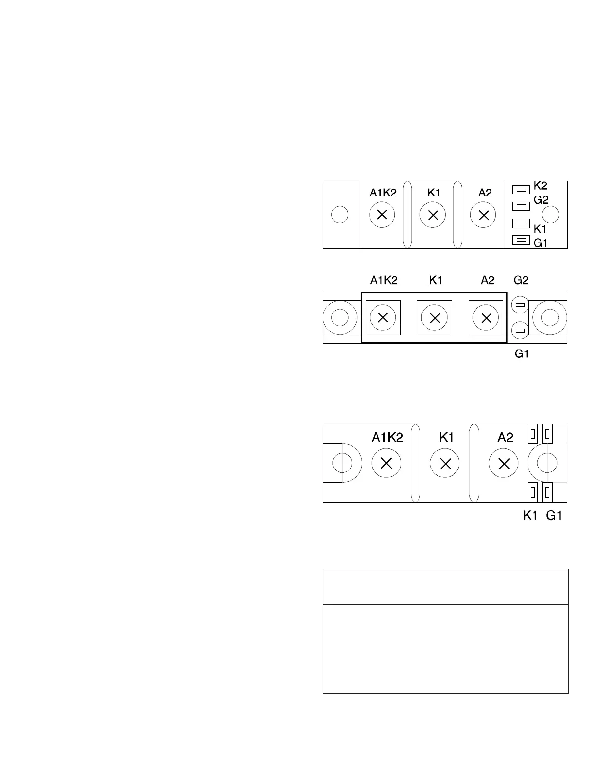
INPUT/OUTPUT SCR MODULESINPUT/OUTPUT SCR MODULES
INPUT/OUTPUT SCR MODULESINPUT/OUTPUT SCR MODULES
INPUT/OUTPUT SCR MODULES
Input SCR, all models, and
Output SCR 7.5 through 53 amp
1
Either style may be used
Output SCR, 65 through 100 amp
1
1
Refer to the “Output Drive Current” rating on the
plastic cover over control board for this value.
Meter Lead Resistance Reading
Positive Negative (ohms)
A1K2 K1,A2 >10,000
K1, A2 A1K2 >10,000
A1K2 G2 <1,000
G2 A1K2 <1,000
K1 G1 <1,000
G1 K1 <1,000
K2 G2
 Loading...