22
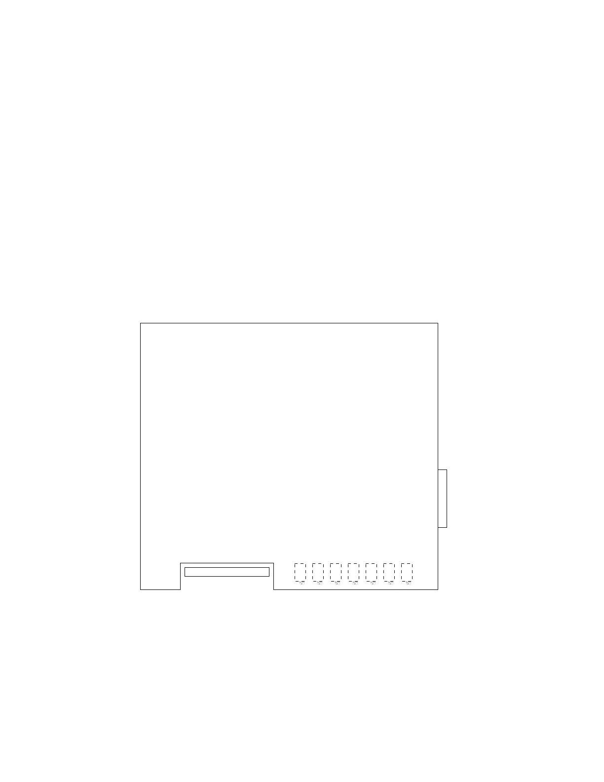
The following calibration potentiometers are located
on the display board. The display board is mounted on
the inside of the door, directly behind the operator's
control panel. These multi-turn potentiometers are
on the side of the display board closest to the door, but
they can be accessed from the bottom of the display
board.
6.106.10
6.106.10
6.10
P1, P2, P3 and P4P1, P2, P3 and P4
P1, P2, P3 and P4P1, P2, P3 and P4
P1, P2, P3 and P4
These potentiometers are for adjusting the output
speed and load signals. The 0 to 10 V DC speed signal
is available at terminal 4TB4-1 and 4TB4-2 of most
drives (see Section 2.14). The load signal is not stan-
dard, and only provided when ordered. Refer to the
specific customer connection diagram if this output
signal was ordered. P1 will set the speed signal gain
(value at maximum speed); P2 the speed signal offset
(value at minimum speed); P3 the output load offset
(value at minimum load); and P4 the output load gain
(value at maximum load
.
6.116.11
6.116.11
6.11
P5, P6 and P7P5, P6 and P7
P5, P6 and P7P5, P6 and P7
P5, P6 and P7
These potentiometers are for calibrating the digital
meter in the operator’s control panel. They are fac-
tory set and should need no further adjustment. P5
will set the maximum reading for output volts; P6 will
set the maximum reading for % speed; and P7 will set
the maximum reading for % load.
P
7
M
e
t
er
Loa
d
C
al
P6 Meter Speed Cal
P5 Meter Output Volts Cal
P4 Output Load Gain
P3 Output Load Offset
P
2
O
ut
put Speed O
ff
set
P1 Output Speed Gain
The Display Board mounts to inside of door behind display.
The potentiometers are mounted towards the door, but can
be accessed from the bottom of the board.
 Loading...