28
NOTE: DO NOT CHANGE MOTOR ROTA-
TION BY USING THE REV SWITCH
ON THE CONTROL CHIP BOARD.
SEE SECTION 7.3.2.
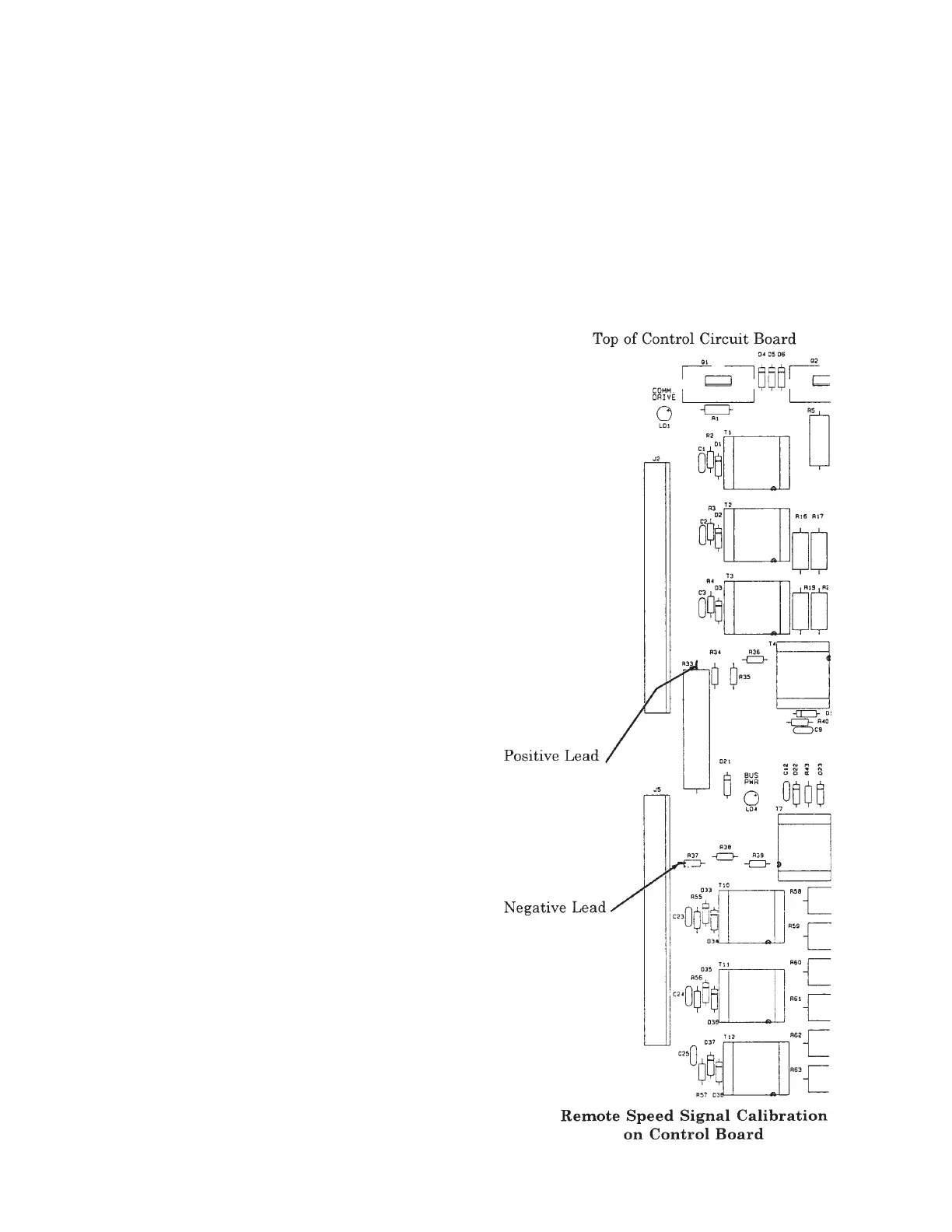
3. Connect the positive lead of a DC voltmeter at
the top of R33 resistor and the negative voltme-
ter lead to the R37 lead closest to J5 terminal
block on the control circuit board. See the
drawing to the right for exact location.
THESE TEST POINTS MAY BE AT ATHESE TEST POINTS MAY BE AT A
THESE TEST POINTS MAY BE AT ATHESE TEST POINTS MAY BE AT A
THESE TEST POINTS MAY BE AT A
DANGEROUSLY HIGH VOLTAGEDANGEROUSLY HIGH VOLTAGE
DANGEROUSLY HIGH VOLTAGEDANGEROUSLY HIGH VOLTAGE
DANGEROUSLY HIGH VOLTAGE
WITH RESPECT TO EACH OTHERWITH RESPECT TO EACH OTHER
WITH RESPECT TO EACH OTHERWITH RESPECT TO EACH OTHER
WITH RESPECT TO EACH OTHER
AND WITH RESPECT TO EARTHAND WITH RESPECT TO EARTH
AND WITH RESPECT TO EARTHAND WITH RESPECT TO EARTH
AND WITH RESPECT TO EARTH
GROUND.GROUND.
GROUND.GROUND.
GROUND.
4. Press the REM push button of the SPEED
SELECT switch. Command the automatic con-
trol system to transmit the minimum speed
command signal (Example: 4 mA on a 4 to 20
mA control system) to terminals 13 and 14 of
terminal strip 4TB4. Adjust the OFFSET po-
tentiometer until the voltmeter begins to in-
crease. Then slowly reverse the adjustment of
the OFFSET potentiometer until the voltme-
ter just reaches its minimum value. This ad-
justment fine tunes the drive’s remote cir-
cuitry to match the automatic control system.
5. Transmit the maximum speed command sig-
nal from the automatic control system (Ex-
ample: 20 mA on a 4 to 20 mA control system)
to terminals 13 and 14 of terminal strip 4TB4.
Adjust the GAIN potentiometer CCW until
the voltmeter begins to decrease in voltage.
Then adjust until the voltage on the meter
just reaches its maximum value.
6. Repeat steps 3 and 4.
7. With the automatic control system still send-
ing its maximum speed command signal, ad-
just the MAX SPEED potentiometer for the
desired maximum speed by noting the voltage
on the DC volt meter. The following table
shows the voltage for a maximum speed for
various drive voltages. If a reduced maximum
speed is desired, the DC volt meter reading
will be proportionally lower.
Drive Voltage DC Voltage at
Maximum Speed
575 V AC 750 V DC
460 V AC 600 V DC
230 V AC 300 V DC
208 V AC 270 V DC
NOTE: THE MAXIMUM SPEED POTENTIOM-
ETER LIMITS THE DRIVE'S MAXIMUM
SPEED FOR BOTH LOCAL AND REMOTE
OPERATION.
7. Command the automatic control system to send
its minimum speed command signal. Adjust the
MIN SPEED potentiometer for a DC voltage
which corresponds to the desired speed. For ex-
ample, for a minimum speed of 30% on a 460 V
AC drive, adjust this potentiometer for a read-
ing of 180 V DC. (30% x 600 V DC)
 Loading...