Repair manual GRAMMER seat suspension MSG95EAC – November 2012
Material no. 1 277 338
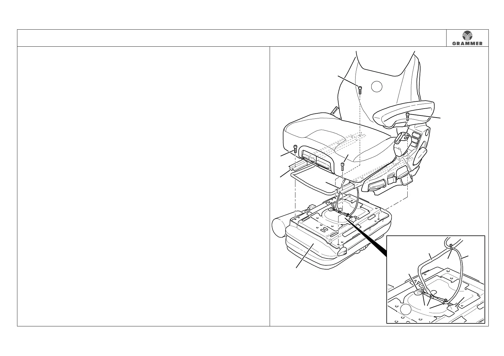
3.1 Seat suspension – removal and installation
Page 1 of 1
Note:
For the removal and installation of the seat
suspension (1) at the vehicle, ask the
vehicle manufacturer for the necessary
assembly work to be carried out.
Removal and installation
1 Push the upper seat part (2) backwards
over the fore/aft adjustment (4) as far
as possible.
2 Mark the screw positioning diagram
and unscrew two hexagon socket
screws (3) at the front of the fore/aft
adjustment (4).
Installation notes:
• Install the fore/aft adjustment (4)
according to the marking.
• Hexagon socket screws (3), 25 Nm.
• Check the fore/aft adjustment (4) for
correct locking in any position.
3 Push the upper seat part (2) forwards
over the fore/aft adjustment (4) as far
as possible.
4 Mark the screw positioning diagram
and unscrew two hexagon socket
screws (3) at the rear of the fore/aft
adjustment (4).
Installation notes:
• Install the fore/aft adjustment (4)
according to the marking.
• Hexagon socket screws (3), 25 Nm.
5 Mark the route of the cable harness of
the upper seat part (6).
6 Mark the points where the cable
harness of the upper seat part (6) is
secured with four cable ties (5) and
remove the cable ties (5).
7 Disconnect the electrical connection (I
and J).
Installation note:
Run the cable harness of the upper
seat part (6) and secure it with cable
ties (5) according to the marking.
8 Lift the upper seat part (2) from the
seat suspension (1).
9 Re-install the components in the
reverse order of their removal.
2845
1
5
5
6
6
I
J
2
1
4
4
3
3
3
3