Grandstream Networks, Inc. GXP User Manual Page 5 of 44
Firmware 1.2.5.3 Last Updated: 03/2011
Installation
EQUIPMENT PACKAGING
Table 1: Equipment Packaging
CONNECTING YOUR PHONE
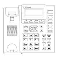
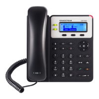
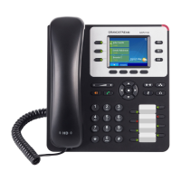
The connectors of the GXP1200/2010/2020 are located on the bottom of the device while they are located on
the back side of the GXP280/285/2000.
Table 2: GXP Connectors
Connects the GXP Extension unit directly to the GXP using connection cable.
Draws power from PoE if provided by network.
10/100Mbps RJ-45 ports for PC (downlink) connection.
LAN
10/100Mbps RJ-45 port for LAN (uplink) connection. Supports PoE (802.3af).
Draws power from either spare line or signal line.
5V DC power port; UL Certified
Headset Jack
RJ22 and 2.5mm for GXP-280/285/2010/2020
RJ22 for GXP-1200
2.5mm for GXP-2000 HW Rev1.0 or later
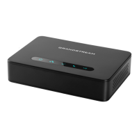
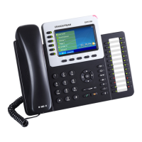
GXP-2000 EXTENSION UNIT
GXP–2000 supports two (2) extension units, providing up to 112 additional programmable extensions. Each
GXP Extension unit has 56 multi–purpose keys, dual color LEDs (red/green) and support BLF (Busy Lamp
Field) and Presence.
GXP–2000 Extension package contains:
 Loading...