~3~
~4~
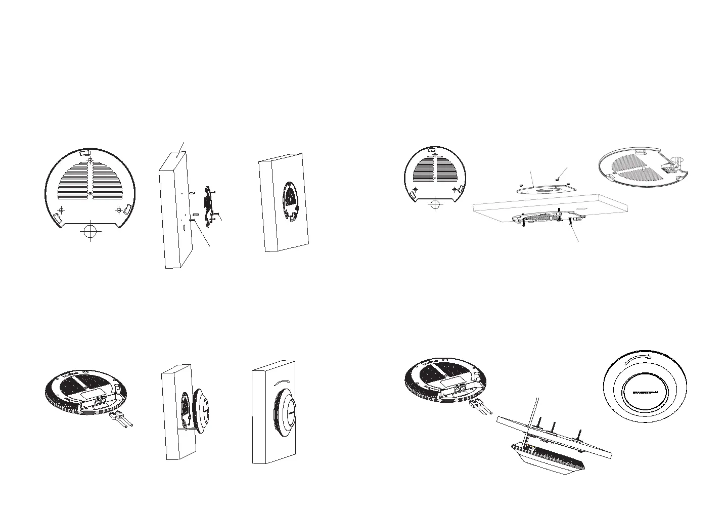
Ceiling Mount
1. Connect the Ethernet cable (RJ45) to the correct ports of your
GWN7630.
2. Align the arrow on the GWN7630AP with the arrow on the locking
tab of the mounting bracket and ensure that your GWN is rmly
seated on the mounting bracket.
3. Turn the GWN clockwise until it locks into place and ts the locking
tab.
4. Connect the power cable and the ethernet cable (RJ45) to the cor-
rect ports of your GWN7630.
5. Align the arrow on the GWN7630AP with the arrow on the locking tab
of the mounting bracket and ensure that your GWN is rmly seated
on the mounting bracket.
6. Turn the GWN clockwise until it locks into place and ts the locking
tab.
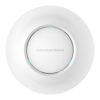
1. Remove the ceiling tile.
2. Place the ceiling backing plate in the center of the ceiling tile and
mark the mounting screw holes (screw holes DIA 5.5mm, reticle
hole DIA 25mm).
3. Insert the screws through the mounting bracket.
1
2
3
4
5
1
2
3
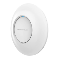
Wall
PA3.5 x 20
Screw
Plastic Expansion
Bolt
6
M3.0x50 screw
M3 nut
Ceiling
Mounting
Note: Ceiling mounting is recommended for optimal coverage perfor-
mance.
Wall
PA3.5x20
Screw
Plastic Expan-
sion Bolt
Wall Mount
4. Connect the Ethernet cable (RJ45) to the correct ports of your
GWN7630.
5. Align the arrow on the GWN7630AP with the arrow on the locking
tab of the mounting bracket and ensure that your GWN is rmly
seated on the mounting bracket and connect the network and power
cables.
6. Turn the GWN clockwise until it locks into place and ts the locking
tab.
4
5
6
 Loading...