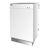
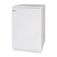
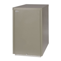
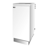
Combi 70 & Combi 90 Oil Boilers
10
Conventional flue models are supplied in one pack,
containing the cased boiler with the burner and control
panel fitted, and literature pack.
Balanced flue models are supplied in two packs,
containing the following:-
Carton 1 The cased boiler with burner and control
panel fitted, and literature pack.
Carton 2 The balanced flue kit - low, high level or
vertical, as ordered. A terminal guard is
supplied with a low level flue kit.
The following flue kits are available, refer to section
3.8 for further details.
a Low level concentric balanced flue.
b Low level concentric balanced flue extensions,
225 mm, 450 mm and 675 mm.
c 90° concentric bend.
d High level balanced flue.
e High level balanced flue extensions.
f Low level balanced flue - square.
(Short, Standard, Long or Extra Long)
g Vertical balanced flue.
h Vertical balanced flue extensions.
i 45° elbows for high level and vertical balanced flues.
3.4.1 Fuel storage
A painted (outside only) storage tank must be
constructed to BS 799:5:1987 and should include the
following:-
a A fuel level gauge (not a glass type).
b A vent pipe incorporating a weatherproof
termination (bend or cap) of a diameter not less
than the filling pipe.
c A sludge valve.
d An outlet valve at the opposite end of the tank
to the sludge valve.
The tank should be positioned in accordance with the
recommendations given in BS 5410:1:1997, which
gives details of filling, maintenance and protection
from fire.
The tank should be suitably supported so as to obtain a
slope of 20 mm per metre towards the sludge valve.
A galvanised tank must not be used.
A plastic tank may be used and must comply with OFS
T100.
3 - GENERAL BOILER INFORMATION
Note: Plastic tanks should be adequately and uniformly
supported on a smooth level surface, across their entire
base area.
3.4.2 Fuel pipes
1 Fuel supply pipes should be of copper tubing with
an internal diameter of at least 8 mm.
Galvanised pipe must not be used.
2 Flexible pipes must not be used outside the boiler case.
3 A remote sensing fire valve must be installed in the
fuel supply line (outside) where it enters the building.
Recommendations are given in BS 5410:1:1997.
4 A metal bowl type filter with a replaceable micronic
filter must be fitted in the fuel supply line adjacent to
the boiler. A shut-off valve should be fitted before the
filter, to allow the filter to be serviced.
5 A flexible fuel line, adaptor and
1
/
4
" BSP isolation
valve are supplied loose with the boiler for the
final connection to the burner. If a two pipe system
or Tiger Loop system is used, an additional flexible
fuel line (900 mm) and
3
/
8
" to
1
/
4
" BSP male
adaptor are available from Grant Engineering (UK)
Limited (Part No. RBS104).
6 The flexible fuel lines supplied should be inspected
annually when the boiler is serviced and replaced
at least every two years.
7 The use of a 'Tankmaster' and Tiger Loop is an
ideal way of delivering an oil supply to the boiler.
The Tankmaster unit, fitted to the storage tank,
includes a filter, sight tube, shut-off valve and fire
valve. A separate fire valve is required in the fuel
line (outside) where it enters the building
containing the boiler. See Fig. 5.
3.4.3 Single pipe system - (See Fig. 3)
1 Where the storage tank outlet is above the burner
the single pipe system should be used. The height
of the tank above the burner limits the length of
pipe run from the tank to the burner.
2 As supplied the burner is suitable for a single pipe system.
3.4.4 Two pipe system - (See Fig. 4)
1 When the storage tank outlet is below the burner, the
two pipe system should be used. The pipe runs should
be as shown in Fig. 4. The return pipe should be at the
same level in the tank as the supply pipe, both being
75 to 100 mm above the base of the tank. The pipe
ends should be a sufficient distance apart so as to
prevent any sediment disturbed by the return entering
the supply pipe.
Delivery
3.3
Fuel supply
3.4

 Loading...


