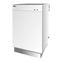
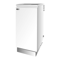
Combi 70 & Combi 90 Oil Boilers
40
Warning: Before replacing any boiler components, set
the boiler On/Off switch to Off, isolate the electrical
supply to the boiler, and close the fuel supply valve.
Allow the boiler to cool.
Refer to Figs. 37 and 38 or 39 for the position of the
boiler components.
1 Manually operate the safety valve on top of the
boiler heat exchanger, to de-pressurise the boiler. It
is not necessary to drain down the heating system.
2 Close the primary return isolating valve (B) and the
pump isolating valve (D). Refer to Fig. 38 or 39.
3 To replace pump head only - Using an Allen key,
remove both screws securing pump head (motor) to
the pump body.
Fig. 36
1
2
3
3
Photocell
8 - BOILER SERVICING
Circulating pump
9.1
9 - REPLACEMENT OF BOILER COMPONENTS
Note: Place an absorbent cloth below the pump
before removing the head to catch the water, and
avoid placing any strain on the electrical cable.
4 Undo the single screw, remove the cover from the
electrical terminal box and disconnect the pump
head from the electrical cable.
5 Fit the replacement pump using the reverse of the
above procedure, ensuring that the new gasket is
correctly fitted between the pump head and body.
6 To replace complete pump - Undo both upper and
lower pump unions, noting the correct direction of
flow (downwards).
7 Undo the single screw, remove the cover from the
electrical terminal box and disconnect the pump
from the electrical cable.
4 Photocell - The photocell is a push-fit in the burner
body, see Fig. 36. Carefully pull out the photocell to
clean.
5 Fan - With the air intake spigot removed, remove the
screws securing the fan housing cover (R/H side of
burner) and remove the cover. Inspect the fan and
housing and clean as necessary. Replace the cover.
6 Pump filter - With the burner cover removed,
remove the four screws securing the pump end
cover. Remove the filter and wash in Kerosene.
Replace the filter and end cover, ensure the 'O' ring
is in position.
7 Control box (see Fig. 36) - With the plastic burner
cover removed, loosen the screw (1) securing the
cover. Open the cover and remove all components.
Remove the oil pump solenoid (2) and loosen the
two screws (3). Move the control box slightly and
disconnect the high voltage leads.
Re-assemble in reverse order.
To ensure safe and efficient operation of the boiler it
is important that re-commissioning is carried out,
especially combustion checks (CO
2
level, flue gas
temperature and smoke number) after the boiler has
been serviced.
Refer to the Commissioning instructions starting on
page 35.

 Loading...


