Solar Pump Station
53
Rp
3
/
4
”
45
G
3
/
4
”
52
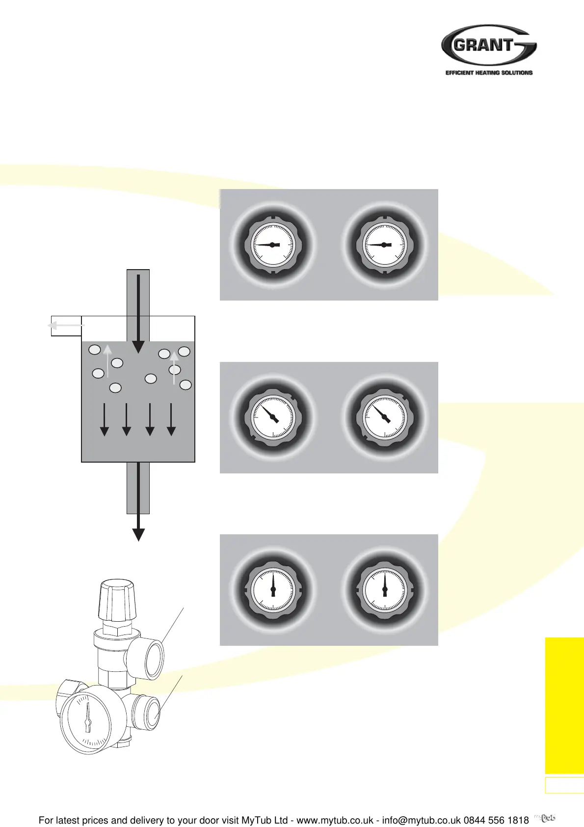
Figure 112: Safety valve and expansion
vessel connections
Air Separator
System Air Venting
• No roof air venting required!
• Expanded cross-section reduces
flow speed
• Venting in “calming zone”
• Upstream installation:
High temperature promotes air
separation
• Hand aspirator for bleeding air.
Figure 111: Air Separator
Figure 114: Gravity Brakes Opened
To fill and completely empty the solar thermal installation, the gravity brake is opened
by turning the handles to the right. The slots in the handles are at an angle of 45°.
Figure 113: Ball Valve Opened
To prevent the circulation of gravity pressure, the gravity brake must be in the operating
position (closed). This means that the slots in the handles are in the vertical position.
Function of Gravity Brakes
Opening pressure of gravity brakes: 20 mbar each.
The gravity brakes are incorporated into both the flow and return ball valve assemblies.
They are operated by turning the handle on the ball valve.
Figure 115: Ball Valve Closed
Turning the handles by 90° to the right. The slots in the handles are in the horizontal
position. The ball valves are closed.