18
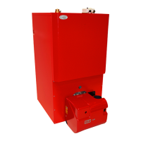
Grant Vortex External Module
4 - GENERAL BOILER INFORMATION
6 Provision should be made to replace water lost
from the system. This can be done manually (where
allowed by the local water undertaking) using an
approved filling loop arrangement incorporating a
double check valve assembly.
7 An automatic air vent should be fitted to the
highest point of the system as the air vent fitted to
the boiler is for venting the boiler only.
8 The system design pressure (cold) should be between
0.5 and 1.0 bar. This pressure is equivalent to the
maximum static head in bar + 0.3 (1 bar = 10.2 metres
of water).
9 All fittings used in the system must be able to
withstand pressures up to 3 bar.
10 Radiator valves must comply with the requirements
of BS 2767(10):1972.
11 One or more drain taps (to BS 2879) must be used
to allow the system to be completely drained.
12 For proprietary expansion vessel/valve/gauge
packs, refer to the manufacturers instructions for
the correct location on the heating system.
13. An automatic filling valve should not be fitted.
Also refer to Sections 6.5 and 6.6.
1 A 15 mm discharge pipe must be connected to the
safety valve outlet connection. The pipework between
the safety valve and the boiler must be unrestricted,
i.e. no valves. The discharge pipe should terminate so
that it cannot cause injury to persons or property.
2 A 15 mm double check valve ballofix type valve is
provided on the flexible filling loop hose for
connection of the cold mains supply to the heating
system. The cold mains supply should terminate
inside the boiler casing.
3 A drain cock is fitted at the bottom on the front of
the boiler to allow the heating system to be drained
4 The expansion vessel is connected via a flexible
hose to allow it to be moved to gain access to the
baffle cleaning cover. When replacing the vessel,
care should be taken to ensure that the flexible
connecting hose is not twisted.
On underfloor systems it is essential that the return
temperature must be maintained above 40° C to
prevent internal corrosion of the boiler water jacket.
General - Grant boilers are compatible with both
copper and plastic pipe. Where plastic pipe is used it
must be of the oxygen barrier type and be of the
correct class (to BS 7291:Part 1:1990) for the
application concerned.
IMPORTANT: The first metre of pipework
connected to both the heating flow and return
connections of the boiler must be made in copper on
all types of system - sealed or open-vented.
Sealed systems - If plastic pipe is to be used, the
installer must check with the plastic pipe manufacturer
that the pipe to be used is suitable for the temperature
and pressures concerned. Pipe must be Class S to BS
7291: Part 1:1990.
Underfloor systems - Plastic pipe may be used on
Underfloor systems where the plastic pipe is fitted
after the thermostatic mixing valve. Copper tube must
be used for at least the first metre of flow and return
primary pipework between the boiler and the
underfloor mixing/blending valves.
Pipework materials
4.12
Underfloor heating systems
4.11
Water connections - Sealed system kit
4.10
 Loading...


