14
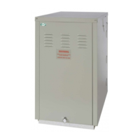
Grant Vortex Outdoor Module
See Fig. 6
If a two pipe system is to be used refer to Section 4.4.6.
1 Remove the oil inlet plug from the fuel pump and
connect the elbow of the flexible fuel line supplied
with the boiler.
2 Connect the flexible fuel line to the rigid supply
using the adaptor supplied. The supply enters
through one of the holes in the underside of the
side casing panels.
1 A 230/240 V ~ 50 Hz mains supply is required.
The boiler must be earthed.
2 The electrical supply to the boiler and control
system should be fed from a single separate 5 Amp
circuit breaker with earth leakage protection,
providing complete electrical isolation.
3 A fused double pole switch or a fused three pin
plug and shuttered outlet socket should be used for
the connection.
4 The power supply cable should be at least 0.75 mm²
PVC as specified in BS 6500, Table 16.
5 All the wiring external to the boiler must be in
accordance with the current I.E.E. Wiring Regulations.
6 Any room thermostat or frost thermostat used must
be suitable for use on mains voltage.
7 The boiler requires a permanent mains supply, do
not interrupt it with any external time control.
8 In the event of an electrical fault after installation
of the boiler, the following electrical system checks
must be carried out:- Short circuit, Polarity, Earth
continuity and Resistance to earth.
1 Outdoor Modules are supplied with a factory fitted
frost protection thermostat, located inside the
boiler control panel. This is pre-wired to the boiler
electrical system and factory set to 5°C.
2 For total system protection against freezing,
particularly during extended periods without
electrical power, Grant recommend the use of a
combined heating system antifreeze and corrosion
inhibitor, used in accordance with the
manufacturer's instructions.
4 - GENERAL BOILER INFORMATION
1 The Outdoor Module must stand on a solid, level
surface capable of supporting the weight of the boiler
when full of water, e.g. a prepared concrete standing,
paving slabs bedded down on sand/cement, or similar.
2 The Module can be installed either against the
building or 'free standing' some distance away from
the building.
3 The Module must be positioned such that the
required clearances from the low level flue outlet,
as shown in Fig. 7, are achieved.
4 Adequate clearance must be left around the
Module for servicing. In particular, a minimum
clearance of 600 mm above the Module for
removal of the top panel and 600 mm at the
opposite end to the flue outlet for access to the
burner.
5 The flue terminal must be a minimum distance of
1.8 m from an oil storage tank.
The flue terminal should be positioned so as to
avoid products of combustion accumulating in
stagnant pockets around the building or entering
into buildings.
General - Grant boilers are compatible with both
copper and plastic pipe. Where plastic pipe is used it
must be of an oxygen barrier type. The first metre of
pipe connected to the boiler must be made in copper.
Sealed systems - Where a sealed heating system is
fitted to the boiler only copper tube may be used.
Underfloor systems - Plastic pipe may be used on
underfloor systems where the plastic pipe is fitted after
the thermostatic mixing valve. Copper tube must be
used for the primary pipework between the boiler and
the underfloor mixing/blending valves.
Connect the fuel supply
4.5
Electricity supply
4.6
Frost protection
4.7
Boiler location
4.8
Pipework materials
4.9

 Loading...


