EasyManuals Logo

Grant VORTEX Pro External Combi 21e User Manual

Grant VORTEX Pro External Combi 21e
56 pages
To Next Page IconTo Next Page
To Previous Page IconTo Previous Page
Page #52 background imageLoading...
Page #52 background image
User Instructions
5
Lighting your Boiler
Before lighting your boiler, ensure that :
There is sufficient fuel in the supply
tank
All fuel supply valves are open.
The water supply is on
The electricity supply to the boiler is
off
The Boiler On/Off switch is set to
OFF
The white pointer on the pressure
gauge is not below the red pointer
The room thermostat is at the
desired setting
The timer or programmer is correctly
set
Switch on the electricity supply to the
boiler.
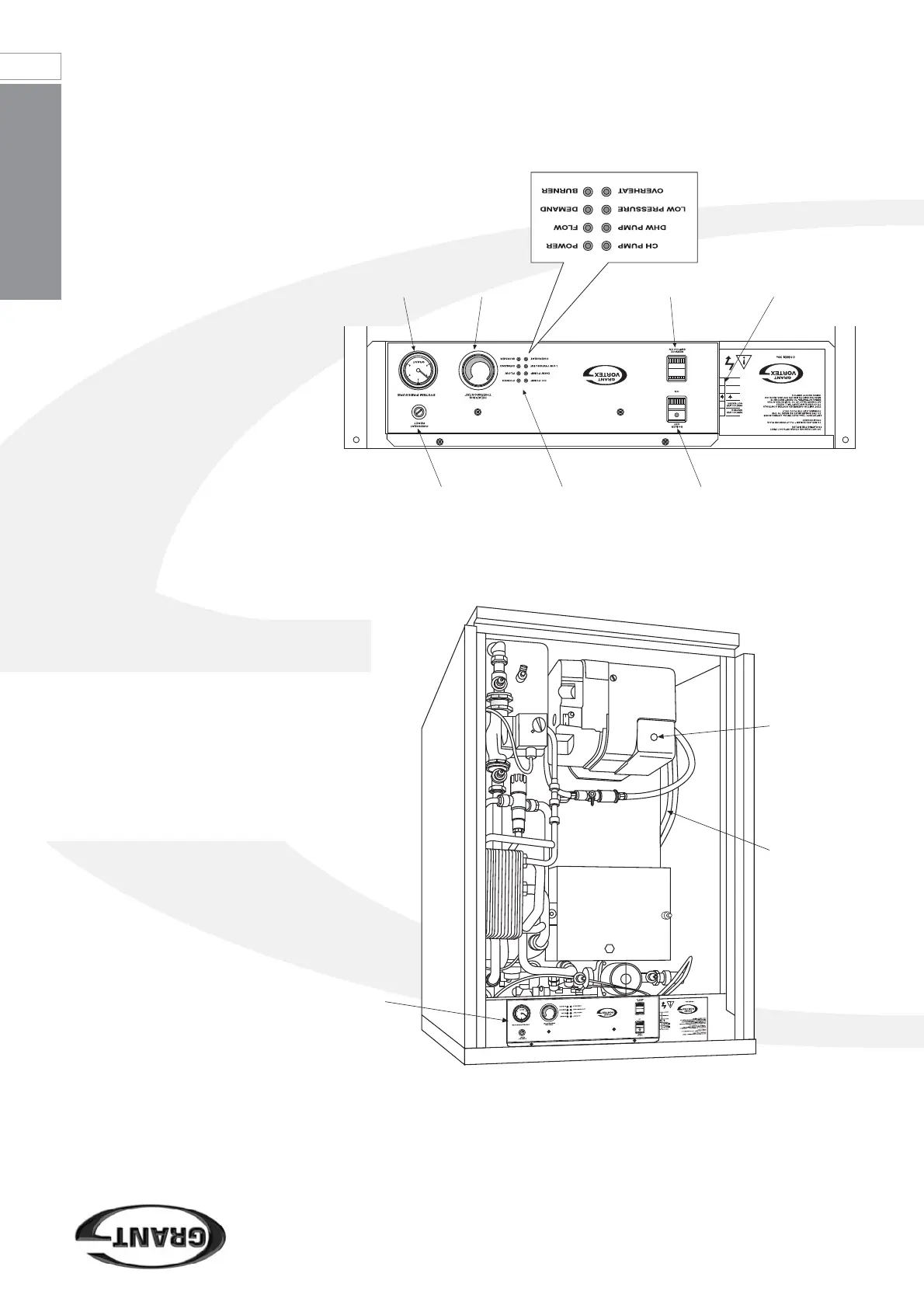
Set the On/Off switch to ON. Refer to
Figure 2.
The boiler will light automatically to heat
the water stored in the boiler. If the
Programmer or Timer is set to a heating
‘on’ period and the room thermostat is
‘calling’ for heat, the boiler will continue
to run to provide central heating, after
the store reaches temperature.
Once the store has reached
temperature, if a hot tap is opened the
boiler will supply hot water.
Turning off your Boiler
For short periods - Set the On/Off
switch to OFF. Refer to Figure 2.
To re-start the boiler, simply set the
switch to ON.
For long periods - Set the On/Off
switch to OFF and switch of the
electricity supply to the boiler. If
required, the fuel supply valve may be
closed and the water and electrical
supplies turned off at the mains. To re-
start the boiler, refer to the full lighting
instructions above.
Figure 2: Vortex Pro External Combi e boiler control panel
I
M
P
O
R
T
A
N
T
C
A
B
L
E
T
O
P
L
U
G
M
U
S
T
B
E
S
E
C
U
R
E
D
I
N
C
A
B
L
E
C
L
A
M
P
B
E
L
O
W
P
A
N
E
L
M
A
X
I
M
U
M
C
A
B
L
E
L
E
N
G
T
H
B
E
T
W
E
E
N
P
L
U
G
A
N
D
C
L
A
M
P
3
5
0
m
m
W
A
R
N
I
N
G
2
3
0
V
I
S
O
L
A
T
E
M
A
I
N
S
P
O
W
E
R
S
U
P
P
L
Y
B
E
F
O
R
E
R
E
M
O
V
I
N
G
C
O
V
E
R
1
2
N
3
N
L
Figure 1: Vortex Pro External Combi 21e boiler with front panel removed
showing position of control panel
Expansion
vessel (In
26e and 36e
models, this
is mounted
on the front
of the boiler)
Burner lock-
out button
Control
panel
IMPORTANT
CABLE TO PLUG MUST BE SECURED IN CABLE CLAMP BELOW PANEL
MAXIMUM CABLE LENGTH BETWEEN PLUG AND CLAMP 350mm
WARNING 230V ISOLATE MAINS POWER SUPPLY BEFORE REMOVING COVER
1
2
N
3
N
L
Electrical connection
socket
Service
switch
Boiler
thermostat
Pressure
gauge
Boiler On / Off switch
Indicator lights
Overheat reset button
(under black cap)

Table of Contents

Questions and Answers:

Question and Answer IconNeed help?

Do you have a question about the Grant VORTEX Pro External Combi 21e and is the answer not in the manual?

Grant VORTEX Pro External Combi 21e Specifications

General IconGeneral
BrandGrant
ModelVORTEX Pro External Combi 21e
CategoryBoiler
LanguageEnglish

Related product manuals