37
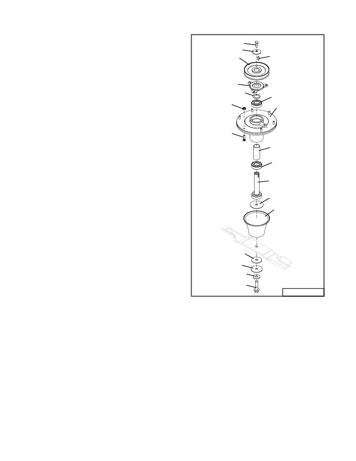
Fig. 22
1
2
3
4
6
7
5
8
6
9
10
12
13
14
15
16
17
18
10128
11
5. Remove belt shields.
6. Remove deck belt. See Deck Belt Re-
placement section above.
7. Remove the top bolt (2) and cup washer (3)
from the spindle sheave (1).
8. Mark spindle sheave (1) on the topside so
it will not be installed upside down on re-as-
sembly.
9. Remove the spindle sheave (1) with a wheel
puller. Make note if you remove any spacers
or washers not shown in the illustration, as
they will need to be reinstalled as they were
removed. Spindle shaft (9) may fall out of the
spindle assembly to the ground after remov-
ing sheave.
10. Remove square key (16) and bearing shield
(4) and save for re-assembly.
11. Remove spindle assembly by removing
the six bolts or nuts (17 or 18) that attach
the spindle housing (7) to the mower deck.
Spindle assembly will fall to the ground if not
supported. Protect spindle housing as nec-
essary.
BLADE SPINDLE ASSEMBLY
REPAIR/REPLACEMENT
(Refer to Fig. 22)
1. Remove blade spindle assembly as de-
scribed previously.
2. Press spindle shaft (9) down through bear-
ings (6) and spindle housing (7).
3. Press bearings (6) out of housing (7) or
remove from shaft (9) as necessary.
4. Visually inspect parts for excessive wear,
corrosion, or damage. Feel parts and ro-
tate bearing races to check for rough spots
or excessive wear.
5. Replace with new parts as necessary.
6. Install lower bearing (6) on spindle shaft
(9).
7. Install bearing spacer (8) on shaft.
8. Install this assembly into housing (7).
9. Press top bearing (6) onto shaft (9) down
against bearing spacer (8).
10. Rotate assembly to make sure shaft
moves freely.
11. Secure spindle assembly to the mower
deck with the six nuts or bolts (17 or 18).
Torque to 21 ft lbs.
12. Install bearing shield (4), square key (16),
sheave (1), cup washer (3) and bolt (2)
in same sequence as removed. Place a
block under the spindle shaft (9) if neces-
sary to hold it up in the spindle housing.
13. Make sure the concave side of the cup
washer (3) is down toward the sheave and
torque top bolt (2) to 38 ft lbs.
14. Rotate assembly to check for free move-
ment.
15. Install deck belt and belt shields.
16. Install blade and tighten bolt (15) to 50-55
ft lbs.