9
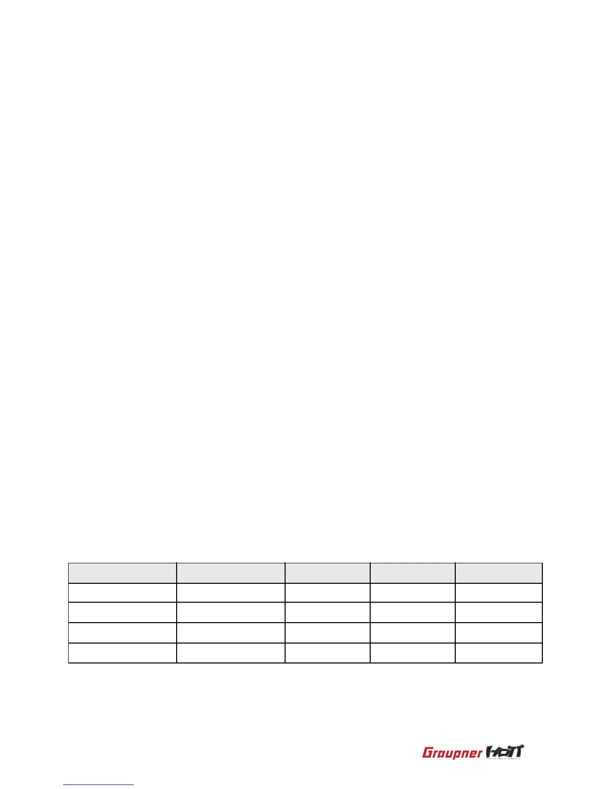
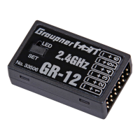
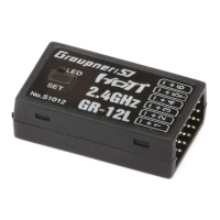
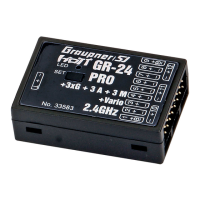
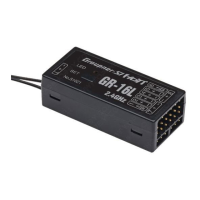
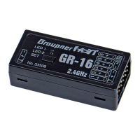
Model Name GR-12S GR-16L GR-24L GR-32L
Channel
Battery channel
Sum signal channel
Telemetry channel
6 channels
Any channel
6
5
8 channels
B
8
T
12 channels
B
8
T
16 channels
B
S
T
1. Servo connection
Plug the servos into the row of sockets on the right end of the receiver. The connector
has polarity, note the small chamfer on one edge. The socket polarity is also marked
as +, - on the case, brown wire (-), red (+) and orange (signal).The servo sockets of the
receiver are numbered and the battery socket and sum signal socket are specied but
the servo can be connected in parallel with a Y-lead for your choice
2. Power supply to the receiver
When using High Power servos, connect the receiver power supply to the vertical ports.
If the servos would be connected to the vertical ports in parallel with the power supply
by a Y-lead, servos also can be controlled.
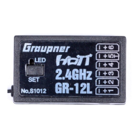
3. The programming socket
The socket with “T” marks on the left end of the receiver is telemetry interface socket,
GR-12S are Channel 5, This socket is used for Telemetry interface by the optional
telemetry sensors, updating the latest Graupner Firmware by the USB interface and
programming by the SMART BOX. The socket polarity is marked as +,- on the case:
brown wire (-), red (+) and orange (T). GR-12S needs the optional adapter cable (Order
No.: 23048)