Do you have a question about the GRAUPNER GR-12S and is the answer not in the manual?
Procedure to establish communication between transmitter and receiver.
Alerts about weak receiver signal or low voltage/temperature.
How to connect servos to the receiver ports.
Connecting power to the receiver for operation.
Details of the telemetry and programming interface socket.
Details on FCC IDs and regulatory conformity for the products.
Compliance statement with FCC rules and conditions for operation.
Testing and compliance notes regarding potential interference.
Equipment compliance with FCC radiation exposure limits.
Certification and registration details from Korean National Radio Research Agency.
This document serves as an operating instruction manual for Graupner HoTT 2.4GHz receivers, compatible with all Graupner transmitters and designed for use in airplanes, helicopters, and gliders. The HoTT system provides real-time telemetry data, enhancing the user's control and awareness during flight.
The Graupner HoTT receivers are designed to provide advanced and reliable radio control for various model aircraft. The core function of these receivers is to establish a secure and robust communication link with a Graupner HoTT transmitter. This link allows for precise control of the model's servos and other functions. A key feature of the HoTT system is its integrated telemetry capabilities. Unlike traditional systems that require separate sensors, the HoTT receivers can directly obtain and transmit useful data such as RPM, voltage, temperature, and user-programmable warnings from compatible telemetric speed controllers. This real-time information is crucial for monitoring the model's status and ensuring safe operation. The system also supports the transmission of data from separate sensor devices if needed.
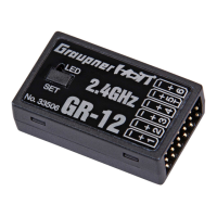
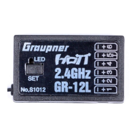
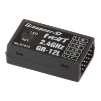
The receivers utilize up to 75 hopping channels, which significantly enhances operating reliability and provides strong immunity to external interference, ensuring a stable connection even in challenging environments. The broad reception voltage range of 3.6 V to 8.4 V (functional down to 2.5 V) ensures full functionality even when the voltage fluctuates, adding to the system's robustness. Two LEDs on the receiver signal its operating status, providing immediate visual feedback to the user.
A critical safety feature is the Fail-safe function. In its default "Hold" mode, if the connection is lost, all channels hold the last given command. However, users can program the throttle channel to a specific fail-safe position (e.g., idle for engine-powered models, stop for electric models, or hold for helicopters). This prevents model crashes and potential personal injury or property damage in the event of signal loss. The system also incorporates a range warning mechanism. If the receiver signal in the down-link channel becomes too weak, the transmitter will emit a single warning beep every second, prompting the user to fly the model back to a safe area. This proactive warning helps prevent loss of control due to insufficient signal strength.
The receivers support binding multiple receivers to a single transmitter in one model. In such a setup, the last bound receiver acts as the master, transmitting all telemetry sensor data through the downlink channel. Additional receivers operate in slave mode, connected in parallel to the master with their downlink channels switched off. This allows for complex control setups, such as using multiple servos for a single control surface, with signals assigned to each receiver via the transmitter's Channel Mapping function or an optional SMART BOX.
Operating the Graupner HoTT receivers involves several key steps, starting with binding the receiver to the transmitter. To bind, both the transmitter and receiver are switched on. The receiver's status LED blinks red until it is bound. The user then enters BIND mode on their specific transmitter and presses and holds the SET button on the receiver for over 3 seconds, causing both red and green status LEDs to blink. Following the transmitter's binding procedures, the system connects within a few seconds, and the receiver's status LED turns solid green, indicating a successful bind. If binding fails, the process can be repeated. It is crucial to double-check that the transmitter is bound to the receiver by cycling the transmitter's power after binding.
Before every flying session, especially with a new model, a ground range check is essential. Graupner transmitters include a range testing system that reduces output power for this purpose. During a range check, the model must be restrained on the ground, and flying is not permitted. After binding, the receiver is mounted in the model, and the RC system is switched on to observe servo movement. The model should be placed on a flat surface with the receiver antenna at least 15 cm above the ground. The user faces the model in their normal flying position, ensuring the transmitter antenna is horizontal and not pointed directly at the model. Entering the range check mode on the transmitter initiates a single beep rhythm, indicating normal processing. The user then walks over 50 meters away, constantly controlling the transmitter sticks to verify normal model operation. Full control should be maintained with the trainer switch pulled. If control issues arise within 50 meters, the system should not be used, and the local Service Department should be contacted. The range check automatically terminates after 90 seconds or when the function is turned off on the transmitter, with the receiver's status LED turning solid green. A ground range of at least 50m is required for safe and reliable model control.
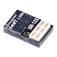
Servo connections are straightforward, with servos plugging into the sockets on the right end of the receiver. The connectors have polarity, marked as +, - on the case (brown wire for negative, red for positive, orange for signal). The servo sockets are numbered, and battery and sum signal sockets are specified. For high-power servos, the receiver power supply should be connected to the vertical ports. Servos can also be controlled by connecting them in parallel with a Y-lead to the vertical ports.
The programming socket, marked "T" on the left end of the receiver, serves multiple purposes. It is used for telemetry interface with optional sensors, updating firmware via a USB interface, and programming with the SMART BOX. The socket polarity is marked similarly to servo connections (brown wire for negative, red for positive, orange for telemetry). For GR-12S receivers, an optional adapter cable (Order No.: 23048) is required for this socket.
To ensure optimal performance and longevity of the Graupner HoTT receivers, certain maintenance and operational guidelines should be followed. Firmware updates are a crucial aspect of maintenance, allowing users to benefit from the latest software improvements and bug fixes. Information on the latest firmware and related software can be found on the Graupner websites (www.openhobby.com, www.graupner-sj.com). To perform a firmware update, optional accessories such as the USB PC Interface (S8270), HoTT PC Interface zender (7168.S), and HoTT Adapter cable (23048) are required.
When operating the radio control system, it is essential to maintain a distance of at least 30 cm between the transmitter antenna and the receiver antenna. If the transmitter antenna is too close, the receiver can be overloaded, causing its status LED to blink red and the transmitter to emit a single beep every second, indicating entry into Fail-Safe mode. Increasing the distance between the antennas to more than 30 cm will cease the beep and turn the receiver's status LED solid green.
For safety, it is critical never to enter the range check mode during normal operations or when controlling a model. The fail-safe function, while programmable via the programming button, is recommended to be set using the SMART BOX. This is because using the programming button for fail-safe settings might reset other values seen on the fail-safe screen in the SMART BOX.
Environmental protection notes emphasize that the product should not be disposed of with other waste. Instead, users are responsible for handing over waste equipment to designated collection points for recycling electrical and electronic equipment. This separate collection and recycling help conserve natural resources and protect human health and the environment. Users can contact their local city office, household waste disposal service, or the place of purchase for information on recycling drop-off points.
Additionally, during operation, the equipment's aerial must be at least 20 cm from any person. No other transmitter should be closer than 20 cm to the equipment to avoid adverse effects on electrical characteristics and radiation patterns. The radio control system should only be operated after the Country setting has been correctly configured on the transmitter, which is essential for compliance with various directives (FCC, ETSI, CE, KC). Always perform a full ground range check before every flight to identify any system or model programming errors. Crucially, never make any changes to the programming of the transmitter or receiver while operating a model.
| Channels | 12 |
|---|---|
| Modulation | HoTT |
| Weight | 12 g |
| Telemetry | Yes |
| HoTT | Yes |