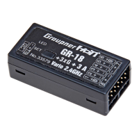
The Graupner HoTT Receiver GR-18 is a versatile receiver designed for multicopter models, specifically racecopters, copters without GPS-supported mode, and 3D copters. This manual covers models No. 33579 (GR-18 + 3G + 3A Vario) and No. S1019 (GR-18L + 3G + 3A without Vario).
Function Description
The GR-18 receiver integrates a gyro system for flight stabilization and control in multicopter applications. It supports various multicopter configurations, including Quadro X, Quadro +, Hexa I, Hexa V, Tri L, Tri R, Hexa-rotor Y, Hexa-rotor IY, Octo-rotor I, Octo-rotor V, and Octo-rotor X. The receiver processes control signals from the transmitter and provides outputs to speed controllers or servos, enabling precise control over the model's flight dynamics.
A key feature is its ability to operate in two main flight modes: "Attitude mode" and "Rate mode." Attitude mode is recommended for beginners, offering a maximal angle limit (e.g., 50° at 100% stick movement) and direct proportional control for Roll and Nick. Rate mode, on the other hand, is an aerobatic mode that allows for rolls and loopings with no angle limit, where stick movement determines the rate of rotation.
The receiver also incorporates telemetry functions, allowing for real-time monitoring of important parameters such as receiver voltage and temperature. The GR-18 + 3G + 3A Vario model (No. 33579) also includes an altitude sensor, providing maximum altitude warnings.
Important Technical Specifications
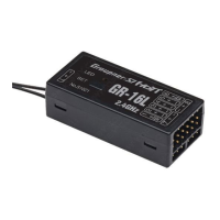
- Model Numbers: 33579 (GR-18 + 3G + 3A Vario), S1019 (GR-18L + 3G + 3A without Vario)
- Compatibility: Graupner HoTT 2.4GHz transmitters
- Channels: Supports up to 8 channels for control signals. Channel 6 can be programmed for a digital sum signal (SUMD). Channel 9 can be used for an extra control channel or a telemetry sensor.
- Cycle Time (Frame Rate): Selectable between 10 ms (for digital servos only) and 20 ms (for analogue or mixed servo setups).
- Telemetry: Integrated telemetry for receiver voltage, temperature, and (for Vario models) altitude.
- Antennas: Two antennas for signal diversity, with signal strength indicators (Ant. 1 - Ant. 2) for optimal positioning.
- Power Supply: The receiver does not have specific battery sockets; power is supplied via servo sockets. Multiple batteries should have the same nominal voltage and capacity, with voltage stabilizing elements (e.g., PRX-5A No. 4136) recommended for different battery types or charge levels.
- Firmware Updates: Performed via the telemetry socket using a PC (Windows XP, Vista, or 7) and a USB interface (No. 7168.6) with an adapter lead (No. 7168.6A or 7168.S).
Usage Features
- Installation: The receiver must be aligned at right angles to the copter on the receiver platform, with its lower surface parallel to one of the copter sides. Double-sided tape (No. S8376) is recommended for secure mounting.
- Binding: The binding process links the receiver to a transmitter's model memory. It involves switching off the transmitter's RF section, powering on the receiver while holding the SET button (LEDs flash), and then initiating binding from the transmitter. A successful bind is indicated by a solid green LED on the receiver.
- Gyro Initialization: Upon power-on, the gyro requires initialization. The model must be kept still for approximately 3 seconds until beeps are emitted by the motors, indicating successful calibration. Motors will not start until calibration is complete.
- Motor Stop Switch: It is crucial to program a motor stop switch on the transmitter to prevent accidental motor starts, especially in Acro 3D mode where a mixer might be needed to ensure motors stop fully backward.
- Throttle Curves: Different throttle curves apply to Attitude and Rate modes. In Acro 3D mode, the throttle stick in the central position is idle, with positive and negative linear ranges for full throttle and full reverse, respectively. In normal mode, the throttle stick in the lowest position is motor stop, with a linear range up to full throttle.
- Safety Features:
- Motor Start Protection: Motors will only start in Attitude mode when the throttle stick is in the lowest quarter. In Rate mode, motors start after the motor stop switch is activated and the throttle is at idle. In Acro 3D mode, motors start after the motor stop switch is activated and the throttle is at a lower position, but only after passing the middle position can speed be controlled regularly.
- Propeller Installation: Propellers should only be installed as the very last step before flight.
- Throttle Course Setting: For safety, the servo travel for throttle should be limited (e.g., -94% to 100%) to ensure motors do not stop during flight.
- No Time Delay: Ensure no time delay is set on the throttle channel in the transmitter's flight phase switching or throttle stick menu, as this disables safety functions.
- Axis Assignment: The receiver's "Axis assign" menu allows for calibration of the gyros and setting their operating direction. This involves briefly moving the roll, nick, and yaw commands on the transmitter and tilting the copter to identify and assign the axes.
- PID Settings (Roll, Nick, Yaw):
- ROLL/NICK P: Adjust in steps of 5 to prevent overshoot during flight.
- ROLL/NICK D: Adjust in steps of 5 for precise engagement on nick and roll, avoiding rapid oscillations.
- DAMPING: Set as low as possible but high enough for optimal PID control. Recommended values vary based on propeller size and controller speed (e.g., 1-2 for 5-6 inch racecopter propellers, 2 for 8 inch propellers, 2 or higher for bigger propellers).
- ROLL FACTOR %: Adjusts roll setting as a percentage of overall gain, useful for asymmetric copters.
- POWER2SENS.: A gyro suppression parameter for strong drives to prevent oscillations at full throttle.
- ROLL/NICK I (Attitude mode): Controls how slowly the copter swings. Reduce if it oscillates after a roll/pitch command.
- AGILITY: Determines the speed at which a new position (yaw rate) is occupied.
- R/N RATE I (Rate mode): Controls the I component of rotation in rate mode. Reduce if it oscillates after a roll/pitch command.
- RATE: Sets the maximum potential rate of rotation in Rate mode.
- Yaw P - Factor: Responsible for the "snap" to yaw. Higher values lead to faster stops but can cause "swinging" if too high.
- Yaw I - Factor: Ensures constant rotations. Increase until rotations are constant, but avoid high values that cause oscillation when stopping.
- Yaw D - Factor: Affects stopping behavior in yaw. Set as low as possible as it impacts the entire system.
- Oneshot: A fast communication protocol between receiver and speed controller, only to be activated if supported by the ESCs. It allows motors to react faster to controls.
- Minpower%: Prevents motors from shutting down in flight. Adjust to ensure motors run smoothly.
- Logging: Allows logging of general attitude control, Euler, and yaw angle to an SD card for evaluation and error analysis.
- CALIBR. POSITION: Calibrates acceleration sensors for horizontal alignment in attitude mode. Place the copter on a level surface and set to "Yes" in the menu.
Maintenance Features
- Care: The product requires no specific maintenance. Protect it from dust, dirt, and moisture. Clean with a dry cloth; do not use detergents.
- Firmware Updates: Regularly check www.graupner.de for the latest firmware versions to ensure optimal performance and access to new features.
- Damage Check: Regularly inspect the receiver for damage to its housing and cables, especially after crashes. A damaged or wet receiver should not be used, even if re-dried.
- Environmental Protection: The product should not be disposed of with household waste. It must be handed over to an applicable collection point for recycling electrical and electronic equipment. Batteries and accumulators must be removed and disposed of at an appropriate collection point.