GRAUPNER GmbH & Co. KG D-73230 KIRCHHEIM/TECK GERMANY
Modifications reserved. No liability for printing errors. 08/2011
- 5 -
the heat-shrink sleeves temporarily over the soldered joints (don’t shrink them), and
carry out a check of the motor function: the motor should spin clockwise (to the right)
as seen from the tail, looking forward. If not, swap over any two of the soldered joints,
and only then use a heat-gun to shrink the sleeves over the soldered joints.
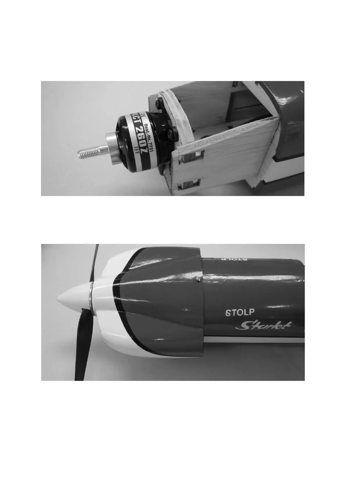
Fix the motor to the firewall using four 3 Ø x 10 mm self-tapping screws (supplied
with the motor). Place the cowl on the fuselage, then slip the spinner backplate on
the propeller driver. At this point you can adjust the position of the motor using the
variable firewall until the spinner lines up correctly with the front of the cowl.
When you are confident that everything fits, drill 2.2 mm Ø pilot-holes in the cowl
before attaching the moulding to the fuselage using three 2.2 Ø x 6.5 mm self-
tapping screws. The position of the bottom two screws can be seen in a later picture;
please refer to the section entitled “The undercarriage”.