GRAUPNER GmbH & Co. KG D-73230 KIRCHHEIM/TECK GERMANY
Änderungen vorbehalten! Keine Haftung für Druckfehler Ident. # 0059200 10.2008
39
use the actuating pushrod which is supplied in the set (M2.5 studding). If you are
fitting the mechanism No. 7890.2 the pushrod must be assembled from a piece of
M2.5 studding, one M2.5 nut and two M2.5 clevises. In either case the length of the
pushrod needs to be set very accurately, i.e. it is essential that the coupling
mechanism locks and releases with complete reliability. The mechanism must be set
up in such a way that the servo is not mechanically obstructed (i.e. stalled) at either
end-point (locked / released).
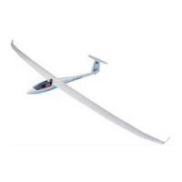
Assembling the VENTUS 2 cx
Fit the wing joiner rod through the fuselage, and slide the inboard wings onto the rod
to the point where the servo leads can be connected. The two inboard wing panels
are held against the fuselage by means of the self-locking wing retainer system. To fit
the outboard wing panels, cut two pieces about 158 mm long from the 12 mm Ø
CFRP dowel supplied in the kit. Now fit the outboard wing panels onto the inboard
panels using the CFRP rods and 4 mm Ø GRP incidence pegs; connect the servo
leads before pushing them fully home. The winglets are attached to the outboard
wing panels by means of two 4 mm Ø GRP pegs. Apply full-length strips of adhesive
tape over the joints between the winglets and the outboard wing panels, top and
bottom, to prevent them working loose.
Connect the clevis on the elevator pushrod to the elevator horn, and fix the tailplane
to the top of the fin using the two M5 socket-head cap screws supplied in the kit.
Balancing the VENTUS 2 cx
Assemble the model completely, ready to fly, and support it at a point about 107 -
111 mm aft of the wing root leading edge on both sides of the fuselage. The model
should now balance level, ideally with the nose inclined slightly down. Lead ballast
will be required in the nose, and this must be fixed to the fuselage permanently and
immovably. Check that the longitudinal dihedral is in the range 1 - 1.5°.
For the first few flights we recommend that you balance the model at the forward end
of the stated CG range.
Check that all the control surfaces are exactly at centre (neutral position) when the
transmitter sticks and trims are at centre.
Control surface travels for the VENTUS 2 cx
Rudder +/- 55 mm
Elevator +/- 10 mm
Ailerons 17 mm up
4 mm down
Centre ailerons 15 mm up
4 mm down
Camber-changing flaps 8 mm up
4 mm down
When an aileron command is given, all the wing flaps should move simultaneously. If
you set the recommended travels, the outboard ailerons will deflect to a greater
extent than the inboard flaps.