GB - 11
Connect Battery
See Battery Removal and Installation on
page 23 and perform steps 2 and 3 in the
installation section.
Place Unit in Operating Position
(Figure 3)
NOTE: T
he seat is shipped with the seat
positioned as far back as possible.
1. Push steering levers aside and tip seat
up.
2. Adjust the seat as needed (see
Adjusting Seat o
n page 15).
3. Remove hardware from top hole of the
steering lever (Figure 3). Slide steering
lever back to align slot with hole at the
top o
f the steering pivot arm.
NOTE: D
o not tighten hardware before
reviewing ADJUSTING STEERING LEVERS
on page 24. If no adjustment is desired
tighten hardware.
4. Adjust steering levers (see ADJUSTING
STEERING LEVERS on
page 24).
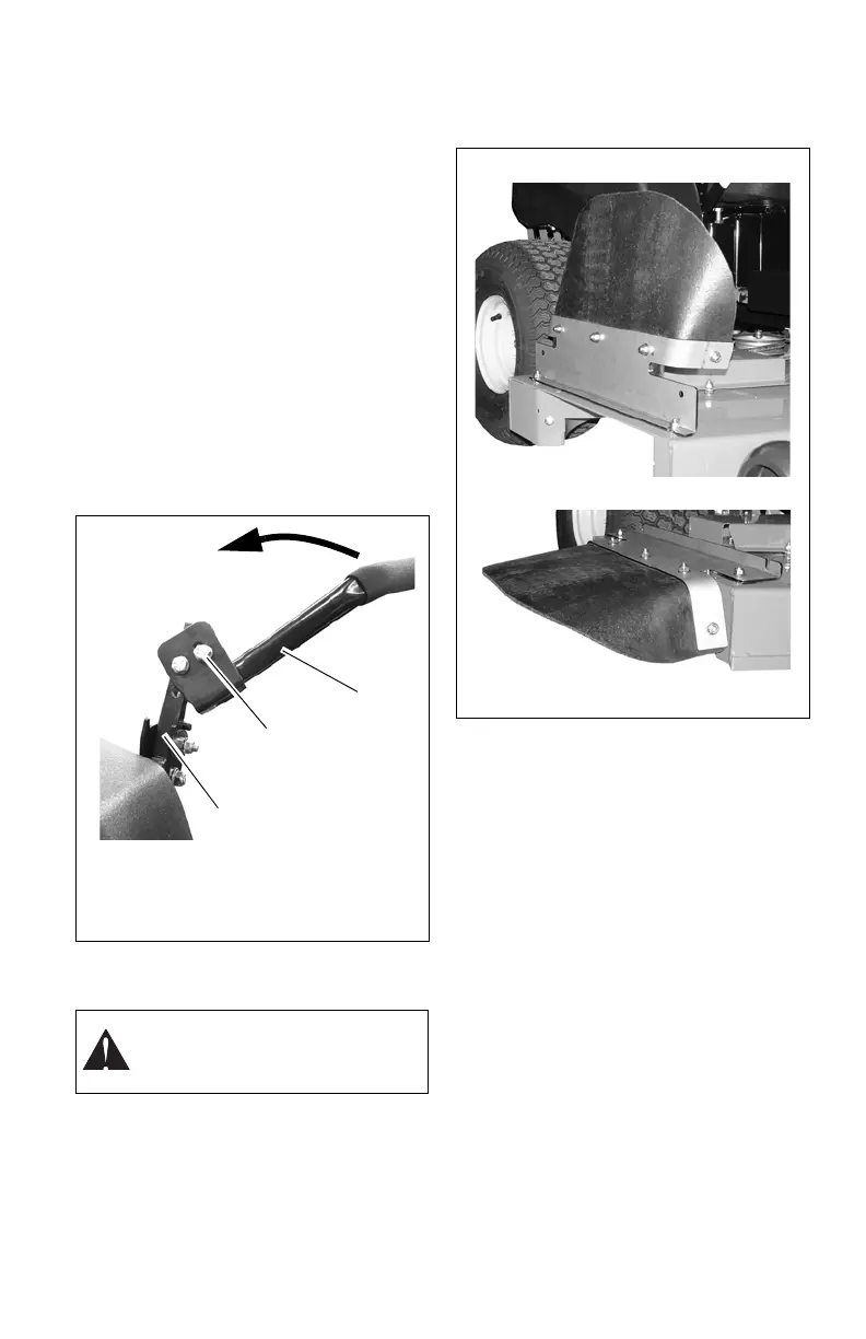
Place Discharge Chute in Operating
Position
Prior to operating the unit, remove the
discharge chute from the transport position
and place the discharge chute in the
operating position (figure 4).
Check Engine Oil Level
Refer to Engine Manual.
Level Mower Deck
See LEVELING AND ADJUSTING PITCH OF
MOWER DECK on p
age 21.
Fill Fuel Tank
Fill fuel tank. DO NOT OVERFILL! See
FILLING FUEL TANK on page 15.
Adjust Seat
See Adjusting Seat on page 15.
WARNING: D
o not operate
mower unless the discharge chute
is in the operating position.
1. Steering Lever
2. Steering Pivot
Arm
3. Steering Lever
Hardware
Figure 3
1
3
2
Figure 4
Transport Position
Operating Position