EN - 31
1. Remove battery from unit. See Remove
Battery on page 30.
2. Place battery on bench or other well-
ventilated place.
3. Connect positive (+) lead of charger to
positive (+) terminal, and negative (–)
lead to negative (–) terminal.
4. Charge battery according to charger and
battery manufacturers’ instructions.
5. Replace battery. See Replace Battery on
page 30.
Jump-Starting
Gravely does not recommend jump-starting
your unit. Jump-starting can damage engine
and electrical system components. See your
engine manual for more detailed information.
ELECTRICAL SERVICE
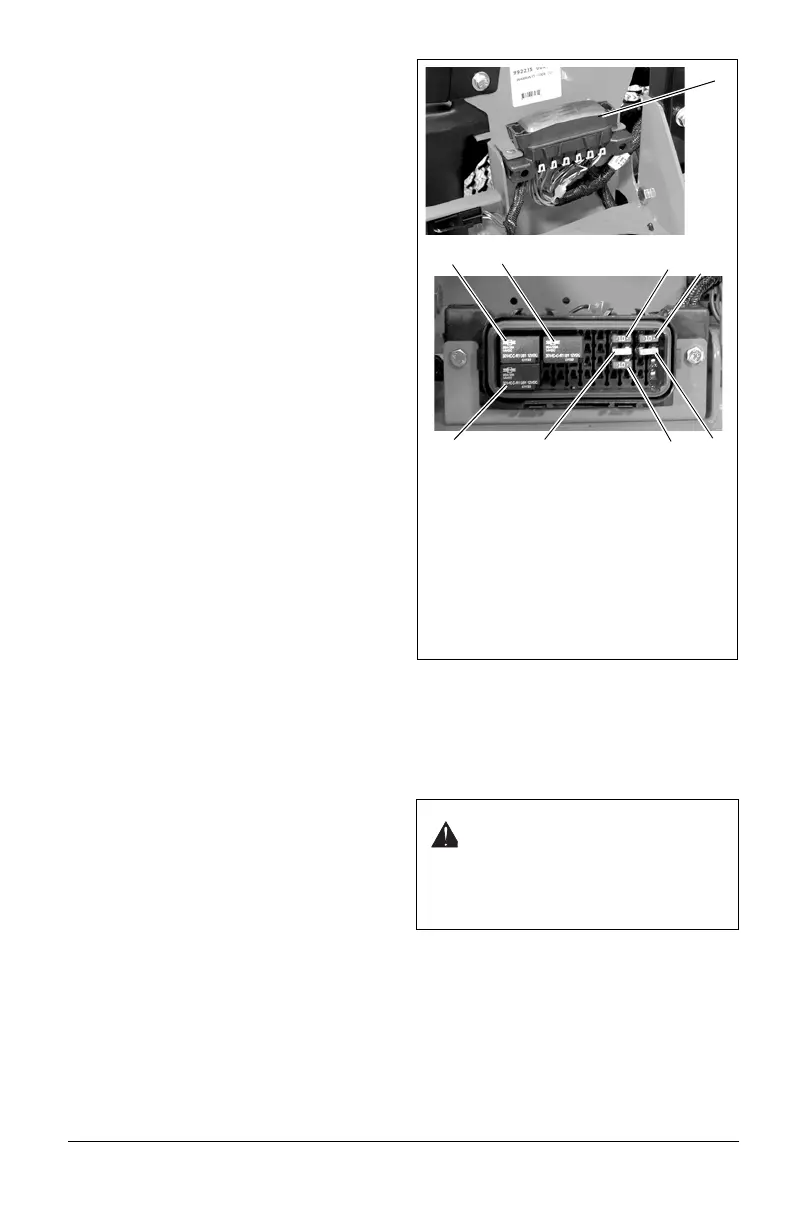
Replacing Fuses
(Figure 19)
IMPORTANT: AVOID DAMAGE! When
replacing fuses use only replacments with the
same amperage rating or you may damage
the circuit.
The unit is equipped with fuses to protect the
multiple circuits. The fuses are located in the
fuse box on the right side of the seat.
1. Remove defective fuse from socket.
2. Check metal clip in fuse window and
discard fuse if clip is broken.
3. Install new fuse of equal amperate rating
into socket.
Replacing Relays
(Figure 19)
NOTICE: (Relays are interchangeable. Use
only quality replacement relays (see Service
Parts on page 44).
The unit is equipped with relays located in the
fuse box on the right side of the seat.
1. Remove defective relay from socket.
2. Install new relay into socket.
STEERING CONTROL NEUTRAL
ADJUSTMENT
Eliminating Excessive Creeping of
the Unit
(Figure 20)
1. If hydraulic system is cold, run unit for a
minimum of five minutes, then shut off
engine.
2. With the unit up to and facing a wall, lift
the unit so that both drive wheels are off
the ground.
3. Remove the drive wheels from the unit.
WARNING: This adjustment
requires operating the engine. Use
extreme care to avoid contact with
moving parts and hot surfaces. Be
sure rear of unit is well supported
and secure before starting engine.
Figure 19
1. Fuse Box
2. Start Relay
3. Starter Solenoid Relay
4. PTO Relay
5. 10-Amp Fuse (Run Circuit)
6. 10-Amp Fuse (Power Seat Circuit)
7. 20-Amp Fuse (Charging Circuit)
8. 10-Amp Fuse (PTO Circuit)
9. 15-Amp Fuse (Auxiliary Circuit)
1
2
3
4
56
78
9