GB - 26
MOWER DECKS
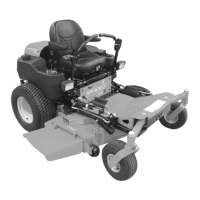
Anti-scalp Roller Adjustment
The anti-scalp rollers are set at the factory for
typical mowing height, but can be adjusted for
high or low cutting conditions (Figure 18).
Anti-Scalp rollers are intended to prevent
lawn scalping, not to control cutting height.
For a very high cutting height, set the anti-
scalp rollers in the lowest position on the
bracket.
For a very low cutting height, set the anti-
scalp rollers in the highest position on the
bracket.
NOTE: There are four anti-scalp rollers on
the outside of the mower deck and four anti-
scalp rollers on the inside of the mower deck.
Make sure all anti-scalp rollers are set at the
same height.
MOWER LIFT PEDAL
ADJUSTMENT
The mower lift pedal can be adjusted to
decrease or increase the amount of force
required to lift the mower deck.
NOTE: Decreasing the amount of force
required to lift the mower deck will increase
the mower deck’s bouncing. Increasing the
amount of force required to lift the mower
deck will decrease the mower deck’s
bouncing.
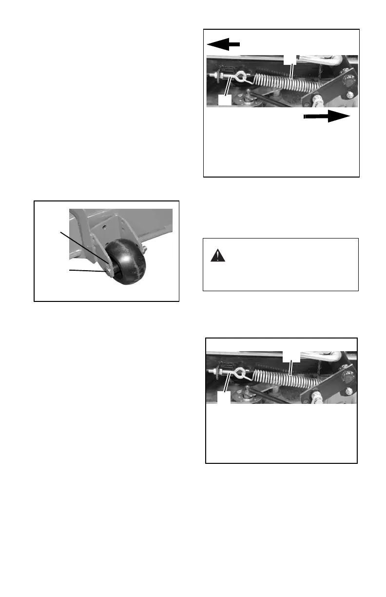
IMPORTANT: Adjust the mechanical lift
spring on each side of the unit to the same
length.
• Adjust the eye-bolt to increase the
length of the mechanical lift spring
which will decrease the amount of
force required to lift the mower deck.
• Adjust the eye-bolt to decrease the
length of the mechanical lift spring
which will increase the amount of force
required to lift the mower deck.
Removing the Mower Deck
NOTE: Only remove PTO belt from electric
clutch.
1. Remove PTO belt from electric clutch
(see Replacing Mower Belts on
page 24).
2. Raise mower deck to transport position
(see Mower Lift Pedal on page 12).
3. Remove mechanical lift spring from each
side of unit (Figure 20).
4. Lower mower deck all the way down.
5. Remove link chains from mower lift arms
(Figure 21).
6. Remove mower mounting arms from
frame.
7. Slide mower deck out from under unit.
Highest
Cutting
Height
Lowest
Cutting
Height
OF3590
Figure 18
CAUTION: Use care when
releasing mechanical lift spring
tension. Keep body parts well
away from springs when
performing this operation.
Figure 19
OF4040
Increased Spring Length =
Decreased Force
Decreased Spring Length =
Increased Force
1
1. Eye-Bolt 2. Mechanical
Lift Spring
2
Figure 20
1. Eye-Bolt 2. Mechanical
Lift Spring
OF4040
1
2