GB - 24
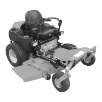
Check Adjustment
NOTE: Be sure to check the parking brake on
both sides of the unit (Figure 14).
With the parking brake engaged, the spring
length should measure 1 1/2 in. (3.81 cm)
between the jam nuts and the trunnion and
the clearance between the return nuts and
trunnion should measure 1/16 to 1/8 in. (1.59
to 3.18 mm). If either of these measurements
is off, adjust the parking brake appropriately.
Adjust the Parking Brake
1. Engage the parking brake.
2. Turn the jam nuts clockwise to compress
the spring or counterclockwise to extend
the spring until there is 1-1/2 in. (3.81
cm) clearance between the jam nuts and
trunnion.
3. Tighten jam nuts together.
4. Turn the return nuts clockwise to
decrease the distance or
counterclockwise to increase the
distance until there is 1/16 to 1/8 in.
(1.59 to 3.18 mm) between the return
nuts and trunnion.
5. Tighten return nuts together.
BELTS
Belt Access
1. Properly stop and park unit (See
OPERATION on page 11).
2. Lower the mower deck.
3. Place seat in most rearward position.
4. Remove belt covers.
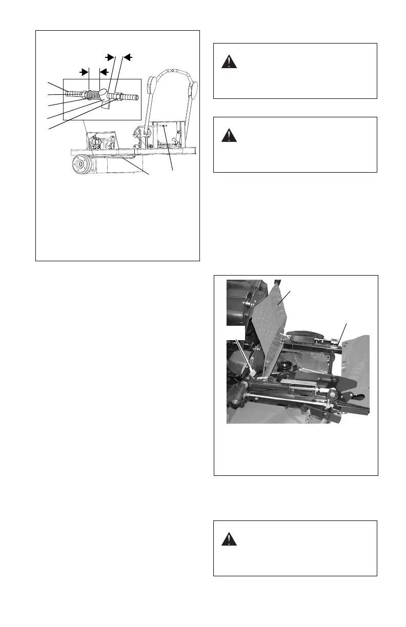
5. Place foot board in open position
(Figure 15).
6. Secure raised footboard with latch.
Replacing Mower Belts
NOTE: Long PTO mower belt must be
removed from blade spindle pulleys prior to
removing short mower drive belt.
1. Parking
Brake Lever
2. Brake Rod
3. Return Nuts
4. Trunnion
5. Spring
6. Jam Nuts
Figure 14
OF3303
1-1/2 in.
(3.81 cm)
1/16 to 1/8 in.
(1.59 to 3.18 mm)
12
3
4
5
6
2
WARNING: MOVING PARTS can
cut or amputate body parts.
ALWAYS wait for moving parts to
stop before performing
maintenance or service.
CAUTION: DAMAGED OR
WORN BELTS may result in
injury and/or damage to unit.
Check belts for excessive wear or
cracks often.
CAUTION: Use care when
releasing idler spring tension.
Keep body parts well away from
idlers when performing this
operation.
Figure 15
1
2
1. Footboard in open position
2. Frame
3. Latch
OF3580
3