SOLDERING EXPERIENCE
For
this
project
to w,ork
properlv, you
rnust have
good
solder
connections.
lf
you
have not had
experience
in
soldering,
it is
suggested that beiore
you
start assembl-
ing this
project, you practice
nraking
solder connections
with
odd
lengths
of
rvire
and used components. Observe
the following rules for
proper
soldering techniques.
l.
Use
a 30-to-5O-watt
pencil
type
soldering
iron. Do
not
use a soldering
gun.
2.
Use
only rosin
core solder as supplied
with
your
project.
The
use of any other types of solder
will
void
your
warranty. lf
additional solder
is requir"ed,
use only 60-.10
rosin
core, such as
Kester
,1.1.
Dt)
NOT
USE
ACID
CORE SOLDER or
paste
f luxes.
3.
Be
sure the tip of the
iron is
well tinned
(coated
with
a thin layer of
molten
solder) so
that it will
properly
conduct
heat. To keep the tip
clean,
wipe
it from
trme to time with a damp sponge or cloth.
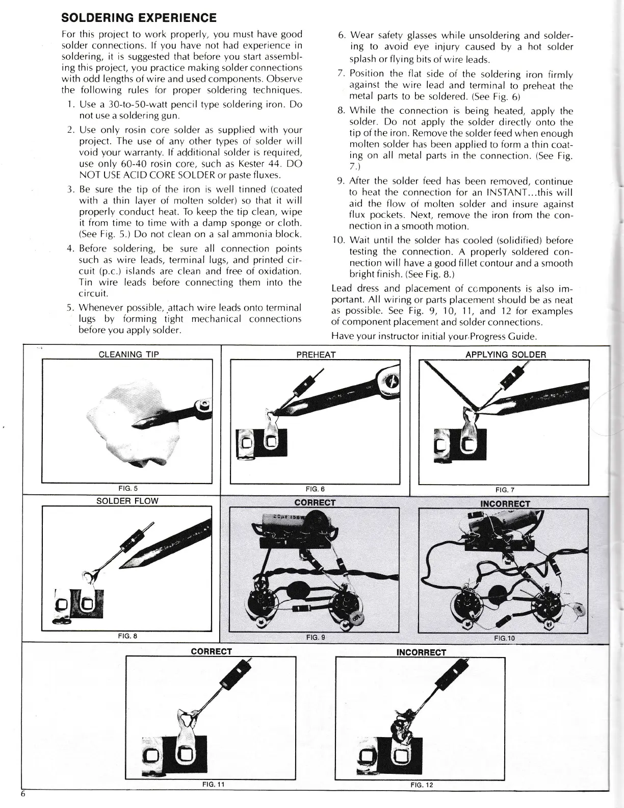
(See
Fig.
5.) Do not clean on a sal ammonia block.
,1.
Before
soldering, be sure all connection
points
such as wire leads, terminal lugs,
and
printed
cir-
cuit
(p.c.)
islands
are clean
and
free
of oxidation.
Trn wire leads
before connecting them
into
the
c
ircu it.
5. Whenever
possible,.attach
wire leads onto terminal
lugs by forming
tight
mechanical
connections
before
you
apply
solder.
6. Wear
safety
glasses
while
unsoldering and solder-
ing
to
avoid eye injury
caused by a
hot
solder
splash
or
flying
bits
of wrre
leads.
7.
Position
the flat
side of the
soldering
iron
firmly
against
thc
wjre lead
and terminal
to
preheat
the
metal parts
to be soldered.
(See
Fig.
6)
B.
While
the
connection is
being heated,
apply the
solder. Do not
apply the
solder directly
onto the
tip
of
the iron.
Remove
the solder
feed
w,hen
enough
molten
solder
has
been
applied to form
a
thrn
coat-
ing
on all nretal
parts
in
the
connection.
(See
Fig.
7.\
9. After
the solder feed has
been removed,
continue
to heat
ihe connection for
an
lNSTANT...this
will
aid the flow
of
molten
solder .tnd insure ag.rinst
flux
pockets.
Next,
remove the iron from
the c-on-
nection
in
a smooth motion.
10.
Wait
until the solder has
cooled
(solidified)
before
testing
the
connection. A
properly
soldered
con-
nection
will have
a
good
fi llet
contour and a smooth
bright
finish.
(See
Fig.
8.)
Lead
dress
and
placement
of ccmponents
is
also im-
portant.
All wiring
or
parts
placement
should be
as
neat
as
possible.
See
Fig.
9,
10,
1-l,
and
12 for
examples
of component
placement
and solder
connections.
Have
your
instructor
initial
your
Progress
Cuide.
APPLYING SOLDER
'i,j.
FIG.7
CLEANING
TIP
I
.l:r
''t.
..;yffi
FIG.
5
PREHEAT
FIG.6
SOLDER
FLOW
FIG. 8
CORRECT
FtG.10
CORRECT
FtG.
11
m
_
i/_.-_.-
-t