DC Inverter Multi VRF System
24
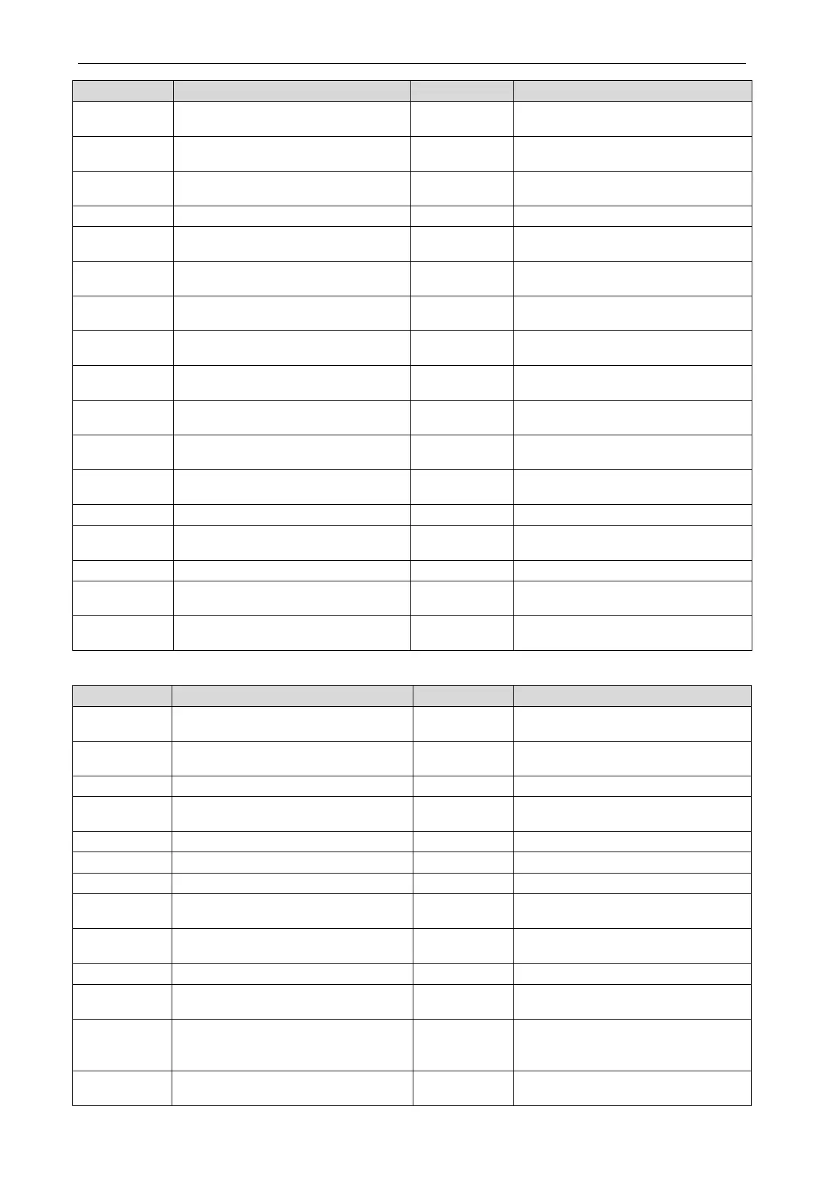
P1
Driving board of compressor operates
H1
Driving board of fan operates
P2
Voltage protection of driving board
power of compressor (uniform)
H2
Voltage protection of driving board
P3
Reset protection of driving module of
H3
Reset protection of driving module of
Drive PFC protection of compressor
Drive PFC protection of fan
P5
Over-current protection of inverter
compressor
H5 Over-current protection of inverter fan
P6
Drive IPM module protection of
H6 Drive IPM module protection of fan
P7
Malfunction of drive temperature
sensor of compressor
H7
Malfunction of drive temperature
sensor of fan
P8
Drive IPM high temperature protection
H8
Drive IPM high temperature protection
P9
Desynchronizing protection of inverter
compressor
H9
Desynchronizing protection of inverter
fan
PH
High-voltage protection of
compressor’s drive DC bus bar
HH
High-voltage protection of fan’s drive
PC
Malfunction of current detection circuit
drive of compressor
HC
Malfunction of current detection circuit
of fan drive
PL
Low voltage protection for DC bus bar
HL
Low voltage protection of bus bar of fan
Phase-lacking of inverter compressor
Phase-lacking of inverter fan
PF
Malfunction of charging loop of driven
HF
Malfunction of charging loop of fan
Failure startup of inverter compressor
Failure startup of inverter fan
PP
AC current protection of inverter
compressor
HP AC current protection of inverter fan
Ed
Low temperature protection for drive
Debugging:
U0
Preheat time of compressor is
C4 Malfunction of lack of IDU
U2
Wrong setting of ODU’s capacity
C5
Alarm because project code of IDU is
Refrigerant-lacking protection
Emergency status of compressor
U5
Wrong address for driving board of
C9 Emergency status of fan
Alarm because valve is abnormal
Rated capacity is too high
Malfunction of pipeline for IDU
Malfunction of lack of main control unit
Malfunction of pipeline for ODU
Rated capacity is too low
UC Setting of main IDU is successful CF
Malfunction of multiple main control
UL Wrong button-dial CJ
Address DIP switch code of system is
shocking
Charging of refrigerant is invalid
Malfunction of multiple wired controller
C0
Communication malfunction between
IDU, ODU and IDU’s wired controller
CU
Communication malfunction between
IDU and the receiving lamp plate
C2
Communication malfunction between
main control and inverter compressor
Cb Overflow distribution of IP address
C3
Communication malfunction between
main control and inverter fan driver
 Loading...
