Gree GMV6 DC Inverter VRF Units Service Manual
238
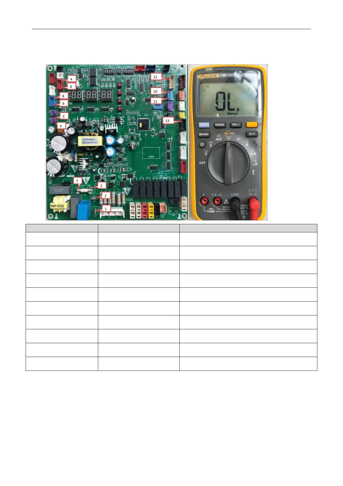
Step 1:
Disconnect the power and wait five minutes.
Step 2:
As shown in the figure, switch the multimeter to the diode gear. Point the black and red
probes to the following positions to check if the main board is normal.
X5 (1) X4 (2)
The main board is normal if the multimeter does not
beep.
CN9 (3) CN9 (4)
The main board is normal if the multimeter does not
beep.
Anode of fuse (2) Cathode of fuse (7)
The fuse is damaged and needs to be replaced if the
multimeter does not beep.
CN1 (4) CN1 (6)
The main board is normal if the multimeter does not
beep.
CN12 (8) CN12 (9)
The main board is normal if the multimeter does not
beep.
CN58 (11) CN58 (10)
The main board is normal if the multimeter does not
beep.
CN54 (12)
The main board is normal if the multimeter does not
beep.
CN17 (13)
The main board is normal if the multimeter does not
beep.
CN54 (12)
The main board is normal if the multimeter does not
beep.
CN17 (13)
The main board is normal if the multimeter does not
beep.
 Loading...

