Gree GMV6 DC Inverter VRF Units Service Manual
263
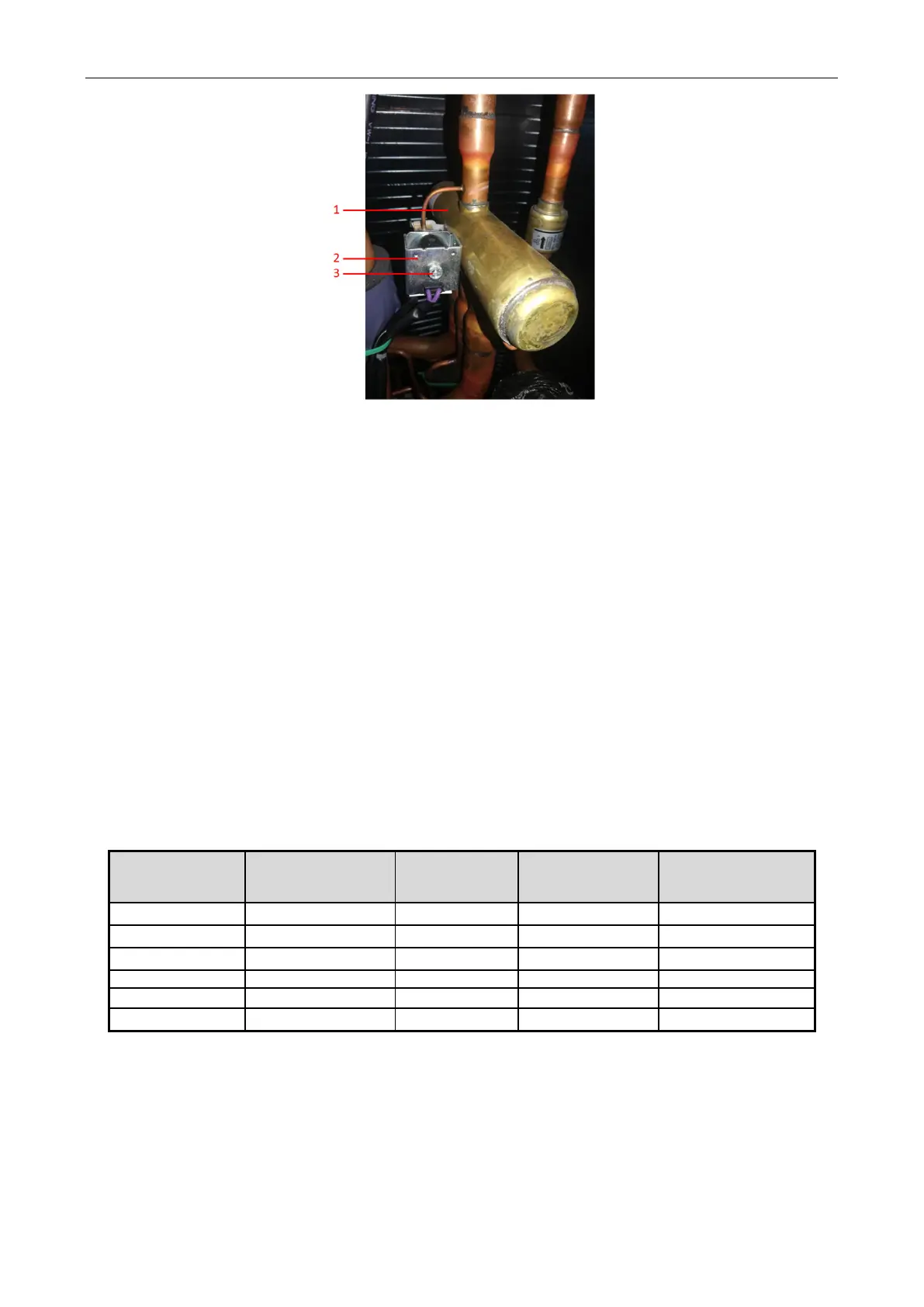
1 --- 4-way valve 2 --- 4-way valve coil 3 --- Screw
Installation procedure
(1) Install the new 4-way valve coil to the exact position.
(2) Tighten the screw with a screwdriver to ensure that the 4-way valve coil does not rotate.
5.5 Removing and Installing Four-way Valve Coil
Preparations
(1) Use the power circuit breaker to switch off the power of the GMV6 VRF system.
(2) Make sure that the unit pipeline system is free of refrigerant.
(3) Remove the unit’s front panel by referring to 5.1.1 Removing the Unit Panel.
Removing procedure
(1) Remove the 4-way valve coil by referring to 5.4 Replacing 4-way Valve Coil (YV1).
(2) Use gas welding to heat the four-port (DESC) connecting pipe of the 4-way valve and pull
them off the 4-way valve. Nitrogen protection should be applied during welding. Refer to Table 1 for
nitrogen pressure.
Table 1 Nitrogen Pressure for Pipeline Assembly Welding
(mm)
Nitrogen pressure
range (MPa)
Pipe length (m)
Shortest pre-charge
time (s)
nitrogen charging time
Φ6~Φ9.52 0.01~0.05 ≤2 10 10
Φ12~Φ16 0.01~0.08 ≤2 15 20
(1) Before the 4-way valve is welded, record the direction of the 4-way valve and the installation
position of each nozzle.
Note:
When welding, wrap the surrounding components with a damp cloth carefully, and do not get the
other components burnt.
(2) Remove the old 4-way valve from the pipeline.
 Loading...

