Gree GMV6 DC Inverter VRF Units Service Manual
4.2.3.20 5L Fan Reverse Dust Removal
Setting steps:
Enter the function setting. The master unit displays as follows by default, and other basic modules
display normal working status:
Press the SW1 up button and the SW2 down button to select the corresponding fan reverse dust
removal mode.
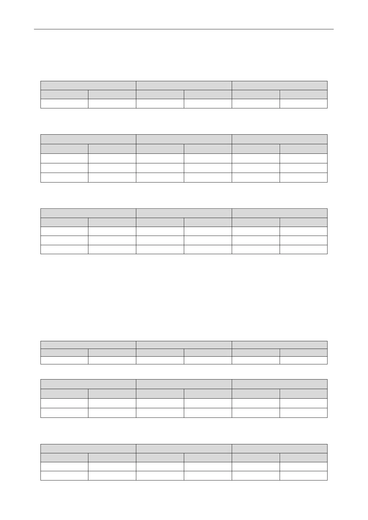
LED1 LED2
LED3
5L On 00 Blinks OC Blinks
5L On 02 Blinks OC Blinks
After selecting the corresponding value, press the SW3 confirm button. The master module displays
as follows:
The master unit memorizes this setting and does not clear it even upon power failure and power-on
again. The default value is 00. Mode 00 indicates the fan reverse dust removal function is turned off, 01
indicates fan reverse dust removal mode 1, and 02 indicates mode 2.
4.2.3.21 5n Fan Anti-Snow
Setting steps:
Enter the function setting. The master unit displays as follows by default, and other basic modules
display normal working status:
Press the SW1 up button and the SW2 down button to select the corresponding fan anti-snow mode.
Function code Display status Current process Display status Current status Display status
5n On 01
Blinks OC Blinks
After selecting the corresponding value, press the SW3 confirm button. The master module displays
as follows:
 Loading...

