GMV DC Inverter VRF
59
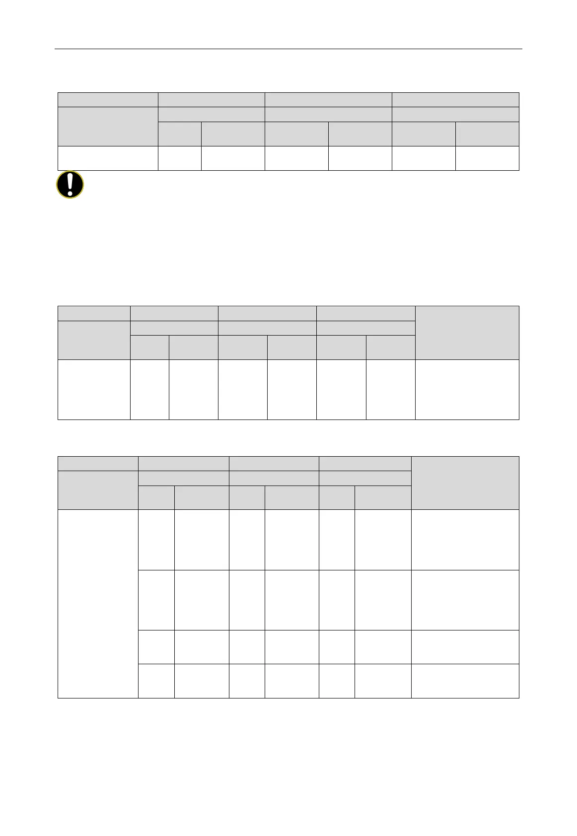
After 30s of display, the display is as follows; if press SW3 button within 30s, the display is as
follows. The unit automatically enters the next step of debugging:
Progress
Code
Display
Code
Display
Code
Display
04_indoor unit
db ON 04 ON OC ON
NOTE!
It is important to confirm that the number of online indoor unit modules is the same as that of
actual connected indoor units for the project; otherwise it will need to conduct the inspection and
debugging again.
Step 8: Step 05 of the unit debugging is “confirmation of internal communication of outdoor unit”.
If there is no abnormality in the detection, the display is below, and then it automatically enters
the next step of detection.
Meaning
Progress
Code
Display
Code
Display
Code
Display
05_ detect
internal
communication
db ON 05 ON OC ON
Once the system
inspection is
completed, it will enter
into the next step
If an abnormality is detected, it will stay in the current state and manual troubleshooting is
required. The corresponding faults are as below:
—— Debugging code Progress code Status code
Meaning
Progress
Code
Display
Code
Display
Code
Display
05_ detect internal
communication
db ON 05 ON C2 ON
The system has detected
“communication
control and inverter
db ON 05 ON C3 ON
The system has detected
“communication
control and inverter fan
db ON 05 ON CH ON
Indoor/outdoor units' rated
capacity ratio is too high.
db ON 05 ON CL ON
Indoor/outdoor units' rated
capacity ratio is too low.
Refer to the part of “Troubleshooting” for the corresponding troubleshooting method.
Step 9: The unit debugging step 06 is “outdoor unit's parts inspection”.
If there is no abnormality in the detection, the display is below, and then it automatically enters
the next step of detection.
 Loading...