GREE GMV5E DC INVERTER VRF UNITS SERVICE MANUAL
274
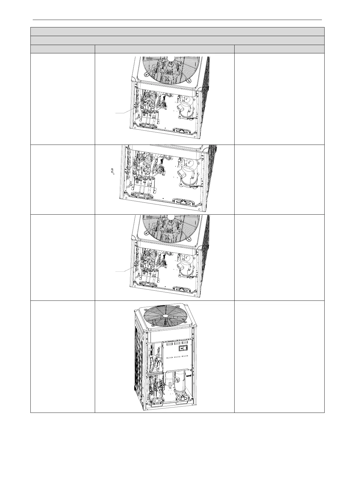
Precondition: No refrigerant exists in the pipeline system and the power supply has been disconnected.
3. Disassemble the
electric expansion
valve.
●Remove the coil from the electric
expansion valve.
●Heat the connecting pipes of the
electric expansion valve by welding
and remove the pipes.
Note: Avoid nearby parts from
being burnt during welding.
4. Remove the electric
expansion valve.
●Remove the electric expansion
valve.
5. Install a new electric
expansion valve.
●
Weld the connecting pipes with
the electric expansion valve.
●
Before welding, cover the valve
with wet cloth.
●During welding, charge nitrogen
into the pipes. The pressure should
be controlled within 0.5±0.1
kgf/cm2 (relative pressure).
Note: Avoid nearby parts from
being burnt during welding.
●
Install the coil on the electric
expansion valve.
6. Fix and wire the
electric box.
●Put the electric box back to
original position and screw it.
●
Connect all lines.
 Loading...

