EasyManua.ls Logo

Gree GMV-N71G/A3A-K User Manual

Gree GMV-N71G/A3A-K
48 pages
To Next Page IconTo Next Page
Page #1 background imageLoading...
Page #1 background image
Owner's Manual
Air Conditioners
Models:
GMV-N22G/A3A-K GMV-N28G/A3A-K GMV-N36G/A3A-K GMV-N45G/A3A-K
GMV-N50G/A3A-K GMV-N56G/A3A-K GMV-N63G/A3A-K GMV-N71G/A3A-K
GMV-N22G/A2A-K GMV-N28G/A2A-K GMV-N36G/A2A-K GMV-N45G/A2A-K
GMV-N50G/A2A-K GMV-N56G/A2A-K GMV-N63G/A2A-K GMV-N71G/A2A-K
GMV-N22G/A4A-K GMV-N28G/A4A-K GMV-N36G/A4A-K GMV-N45G/A4A-K
GMV-N50G/A4A-K GMV-N56G/A4A-K GMV-N63G/A4A-K GMV-N71G/A4A-K
GMV-N22G/A8A-K GMV-N28G/A8A-K GMV-N36G/A8A-K GMV-N45G/A8A-K
GMV-N50G/A8A-K GMV-N56G/A8A-K GMV-N63G/A8A-K GMV-N71G/A8A-K
GMV-N22G/C9A-K GMV-N28G/C9A-K GMV-N36G/C9A-K GMV-N45G/C9A-K
GMV-N50G/C9A-K GMV-N56G/C9A-K GMV-N63G/C9A-K GMV-N71G/C9A-K
GMV-N22G/E3A-K GMV-N28G/E3A-K GMV-N36G/E3A-K GMV-N45G/E3A-K
GMV-N50G/E3A-K GMV-N56G/E3A-K GMV-N63G/E3A-K GMV-N71G/E3A-K
GMV-N22G/A3A-D GMV-N28G/A3A-D GMV-N36G/A3A-D GMV-N45G/A3A-D
GMV-N50G/A3A-D GMV-N56G/A3A-D GMV-N63G/A3A-D GMV-N71G/A3A-D
GMV-N22G/A2A-D GMV-N28G/A2A-D GMV-N36G/A2A-D GMV-N45G/A2A-D
GMV-N50G/A2A-D GMV-N56G/A2A-D GMV-N63G/A2A-D GMV-N71G/A2A-D
GMV-N22G/A4A-D GMV-N28G/A4A-D GMV-N36G/A4A-D GMV-N45G/A4A-D
GMV-N50G/A4A-D GMV-N56G/A4A-D GMV-N63G/A4A-D GMV-N71G/A4A-D
GMV-N22G/A8A-D GMV-N28G/A8A-D GMV-N36G/A8A-D GMV-N45G/A8A-D
GMV-N50G/A8A-D GMV-N56G/A8A-D GMV-N63G/A8A-D GMV-N71G/A8A-D
GMV-N22G/C9A-D GMV-N28G/C9A-D GMV-N36G/C9A-D GMV-N45G/C9A-D
GMV-N50G/C9A-D GMV-N56G/C9A-D GMV-N63G/C9A-D GMV-N71G/C9A-D
GMV-N22G/E3A-D GMV-N28G/E3A-D GMV-N36G/E3A-D GMV-N45G/E3A-D
GMV-N50G/E3A-D GMV-N56G/E3A-D GMV-N63G/E3A-D GMV-N71G/E3A-D
Thank you for choosing Air Conditioners, please read this owner’s manual carefully before
operation and retain it for future reference.If you have lost the Owner’s Manual, please
contact the local agent or visit www.gree.com or sent email to global@gree.com.cn or
electronic version.
GREE reserves the right to interpret this manual which will be subject to any change due to
product improvement without further notice.
GREE Electric Appliances, Inc. of Zhuhai reserves the final right to interpret this manual.
Multi Variable Air Conditioners
Wall Mounted Type Indoor Unit
Copyright 2018. This translation is property of GREE PRODUCTS SL. All rights reserved. Total or partial reproduction without its express authorization is prohibited.

Table of Contents

Other manuals for Gree GMV-N71G/A3A-K

Question and Answer IconNeed help?

Do you have a question about the Gree GMV-N71G/A3A-K and is the answer not in the manual?

Gree GMV-N71G/A3A-K Specifications

General IconGeneral
Cooling Capacity7.1 kW
Heating Capacity8.0 kW
RefrigerantR410A
TypeVRF
Power Supply220-240V, 50Hz
Operating Temperature Range (Heating)-15 ~ 24 °C

Summary

Preface

User Notice

Information regarding the correct disposal of the product.

1 Safety Precautions

2 Product Introduction

2.1 Outline of the Unit and Main Parts

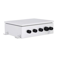
Diagram and list of the primary parts of the indoor unit.

2.2 Rated Operating Condition

Specifies the standard operating conditions for cooling and heating.

3 Preparations for Installation

3.1 Location for Installation

Guidelines for choosing the optimal and safe location to install the indoor unit.

3.2 Schematic diagram of installation spaces

Illustrates the required clearances around the indoor unit for installation.

3.3 Requirements for Communication Line

Specifies the type and length of wiring needed for communication between units.

3.4 Wiring Requirements

Details electrical wiring specifications, including power cord and wire sizes.

4 Installation Instructions

4.1 Installation of Indoor Unit

Provides dimensions and model-specific information for installing the indoor unit.

4.2 The installation of the rear panel

Instructions on how to properly mount the rear panel of the indoor unit.

4.3 Debugging

Procedures for setting the master indoor unit and troubleshooting initial errors.

4.4 Preparation of the piping hole

Guidance on creating the necessary hole in the wall for piping and wiring.

4.5 Installation of the drainage pipe

Instructions for correctly installing the drain pipe for efficient water removal.

4.6 Installation the connection pipes

Steps for connecting the refrigerant pipes to the indoor unit.

5 Wiring Work

5.1 Connect Cables and Terminals of Wiring Board

How to properly connect wires to the unit's terminal board.

5.2 Power Cord Connection

Guidance on connecting the main power cord to the unit.

5.3 Connection of Communication Line of IDU and ODU

Steps for connecting the communication wire between indoor and outdoor units.

5.4 Connection of Communication Line of Wired Controller

Instructions for connecting the communication wire for the wired controller.

5.5 Illuminate for Connection of Wired Controller and Indoor Units Network

Information on connecting wired controllers to the indoor unit network.

5.6 Installation of the indoor unit

Details on the final steps for mounting and securing the indoor unit.

6 The Best Usage Method

7 Maintenance Method

7.1 Cleaning panel

Instructions for removing and cleaning the front panel of the indoor unit.

7.2 Cleaning the air filters

Steps for removing, cleaning, and reinstalling the air filters.

7.3 Check before the usage season

Pre-season checks to ensure the unit is ready for operation.

7.4 Check after the usage season

Post-season checks and procedures for preparing the unit for storage.

8 Table of Error Codes for Indoor Unit

9 Malfunction Analyzing

9.1 Service center

When to contact the service center for specific issues.

9.2 After-sales service

Information on how to seek assistance for quality or other problems.

10 Adjusting Method Of The Air Direction

10.1 Adjusting air direction up and down

Instructions for adjusting the vertical louvers for airflow direction.

10.2 Adjusting air direction left and right

Instructions for adjusting the horizontal louvers for airflow direction.

Related product manuals