MULTI VRF-Ⅱ INDOOR UNIT SERVICE MANUAL EUROPEAN/LATIN AMETICA (R410A)
97
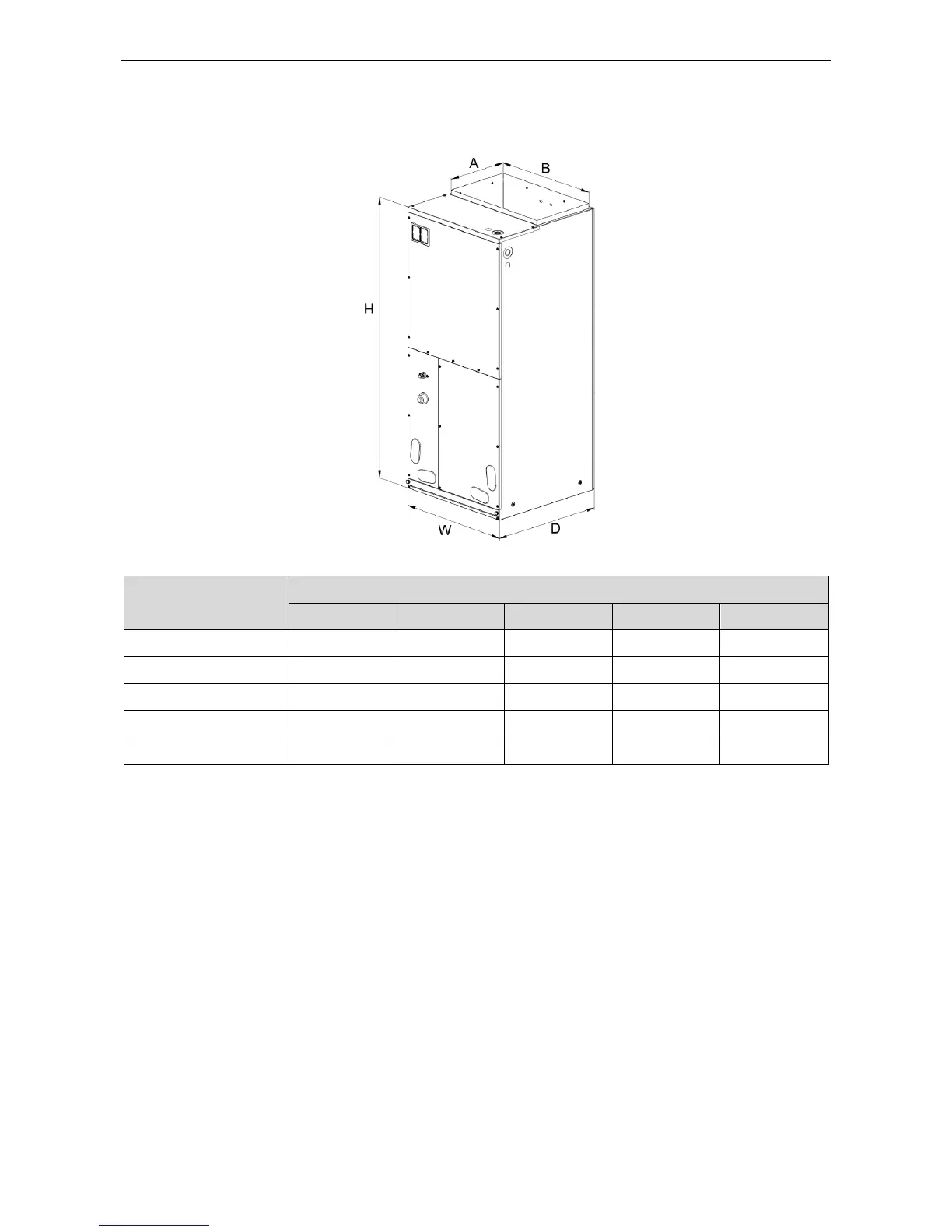
3.11 Installation of Air Handler type Indoor Unit
3.10.1 Outline and installation dimension
Unit: mm
3.10.2 Installation notice
When installing the air handler, take consideration to minimize the length of refrigerant tubing as
much as possible. Do not install the air handler in a location either above or below the condenser that
violates the instructions provided with the condenser. Service clearance is to take precedence. Allow a
minimum of 24” in front of the unit for service clearance. When installing in an area directly over a finished
ceiling (such as an attic), an emergency drain pan is required directly under the unit. See local and state
codes for requirements. When installing this unit in an area that may become wet, elevate the unit with a
sturdy, non-porous material. In installations that may lead to physical damage (i.e. a garage) it is advised
to install a protective barrier to prevent such damage.
This air handler is designed for a complete supply and return ductwork system. Do not operate this
product without all ductwork attached.
Based upon the actual conditions, if air handler is installed as type (A), the air handler should be
concealed in a specific room or space and make sure the air handler is not accessible to the general
public.
Based upon the actual conditions, if air handler is installed as type (B), make sure that there is
enough space for care and maintenance and the height between the air handler and ground is above
2500mm. And the air handler is not accessible to the general public.
 Loading...