5
Multi Variable Air Conditioners Ducted Type Indoor Unit
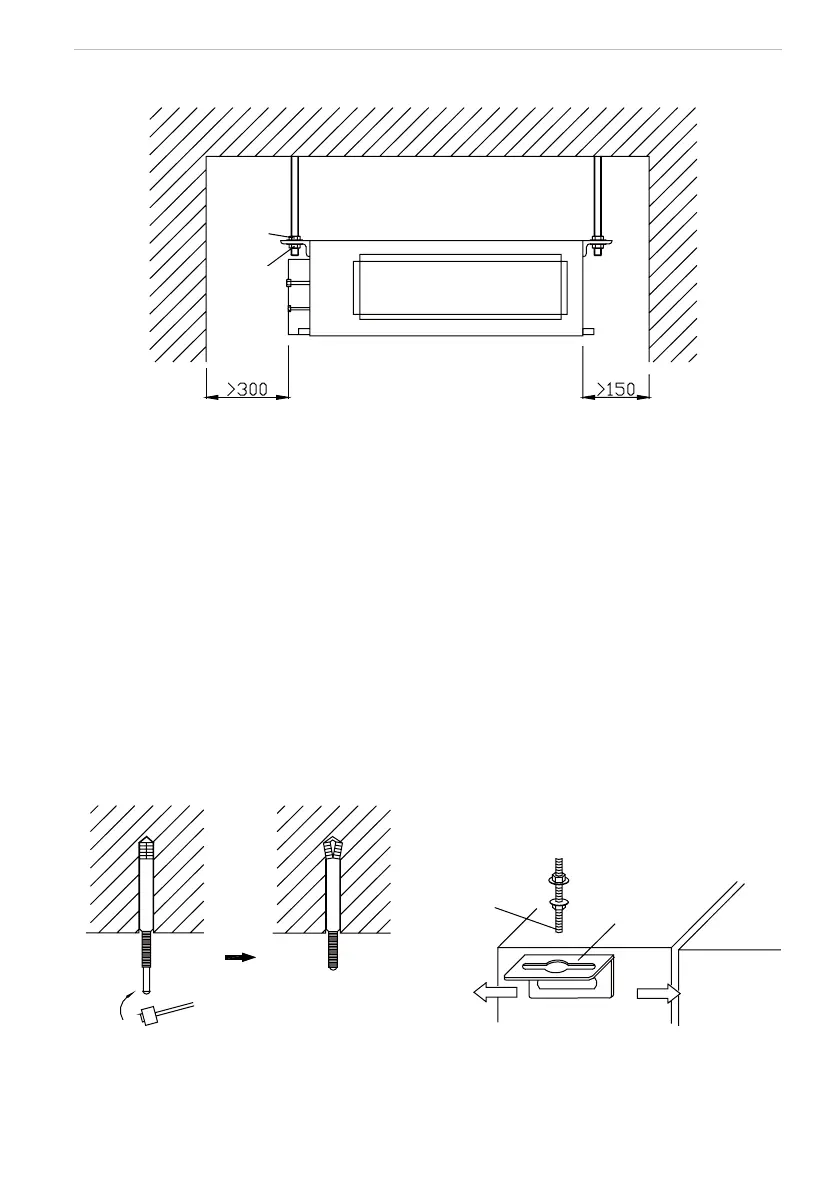
3.2 Schematic diagram of installation spaces
Nut with
washer
Nut spring
pad
Fig.3
3.3 Schematic diagram of installation spaces
A. Ensure that the latches at top are rm enough to stand the weight of unit.
B. Convenience to drain by the drain hose.
C. There is no obstacle around intake and outlet vent to keep good ventilation.
D. Ensure the installation distance of the indoor unit as shown in g.3 and also the necessary space for
care and maintenance.
E. Keep it far from the heater, leakage of combustible gas and place with fume.
F. This unit is the cassette type (hided in the ceiling), as shown in g.6.
G. Indoor unit, outdoor unit, power cord, and connection pipe should keep a distance of at least 1m from
the TV set, radio, so as to prevent incurring image interference and noise on the above mentioned home
appliance. (If the electric wave is strong, even though they are kept 1m apart, noise would still happen.)
3.4 Install the indoor unit
A. Insert the anchor bolt M10 to the hole then nail the iron nails into the bolts. The distance between holes
is shown in g.1. The installation of the anchor bolt is shown in g.4.
Hoisting screw
Hook
Unit
Fig.4 Fig.5
B. Install the hook on the unit, as shown in g.5.
C. Install the indoor unit to the ceiling as shown in g.6.
 Loading...

