Multi Variable Air Conditioners Duct Type Indoor Unit
20
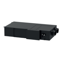
Fig 5.4
Fig 5.5
(4) Secure the communication line with the wire clamp on the electric box.
(5) In order to ensure the reliability of communication between IDU and ODU and the
communication among each IDU, add a matched resistance(supplied in a package before
ex-factory) on the wiring board of the last indoor unit in a series connection. The matched
resistance should be connected in parallel between terminal screw D1 and D2, as shown in
Fig 5.5.
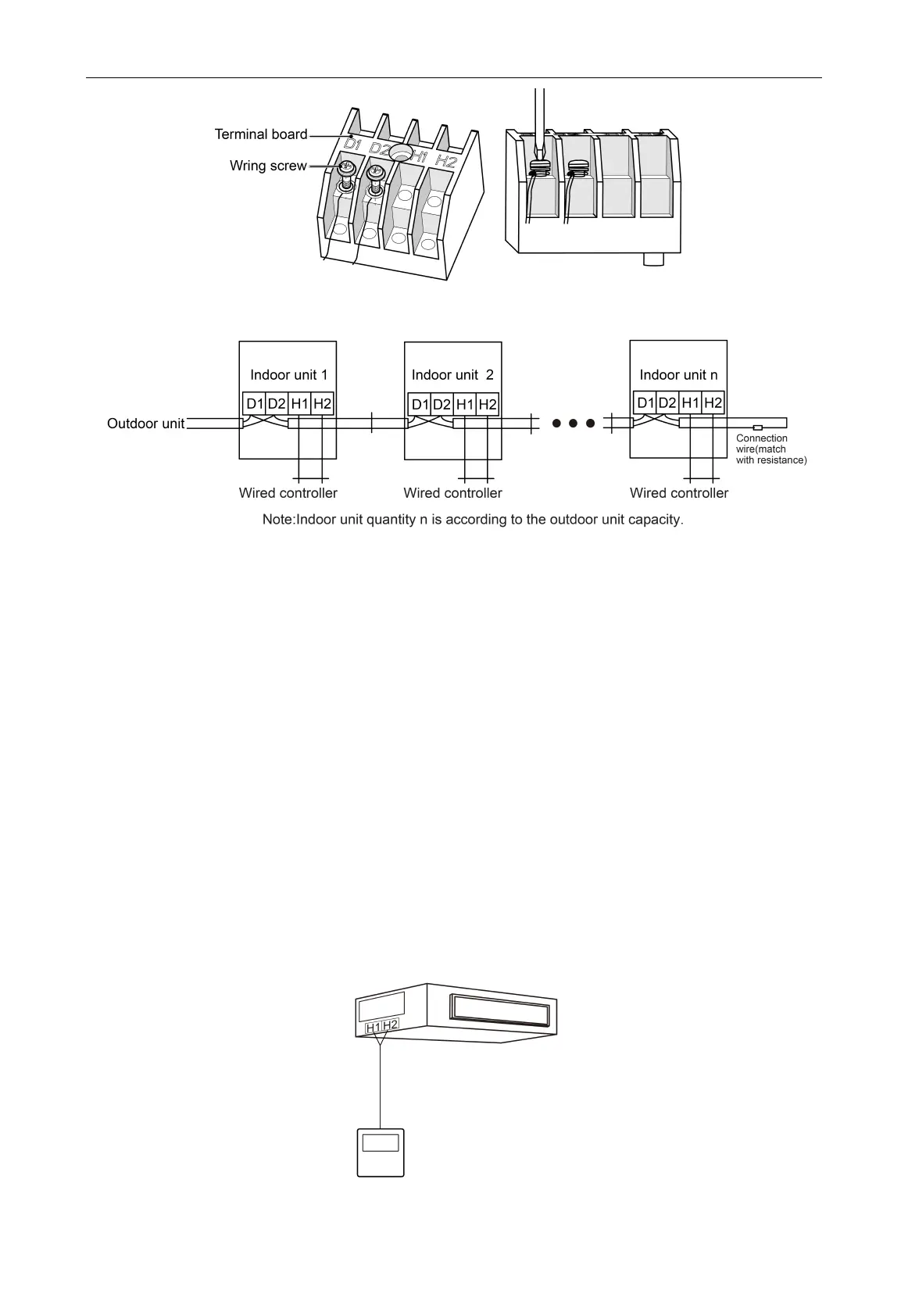
5.4 Connection of Communication Line of Wired Controller
(1) Open the cover of electric box of indoor unit.
(2) Lead the communication line of wired controller across the rubber ring.
(3) Connect the communication line of wired controller to terminal H1 and H2 on the 4-digit wiring
board of indoor unit.
(4) Use a wire clamp to fasten the communication line of wired controller.
(5) Instruction of connection of wired controller.
1) Fig6.6 shows the installation of wired controller.
Fig 5.6

 Loading...