7 PRODUCT
GMV5 COMPACT MULTI VRF UNIT
SERVICE MANUAL
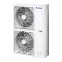
setting is 16℃ for cooling and 30℃ for heating).
a. Variance ratio of cooling capacity
25
0.97
Hm(m)
20
10
Hp(m)
1.0
10
10
20
4020 30 50 60
L(m)
8070 90 100
0.95
0.92
0.90
0.85
0.87
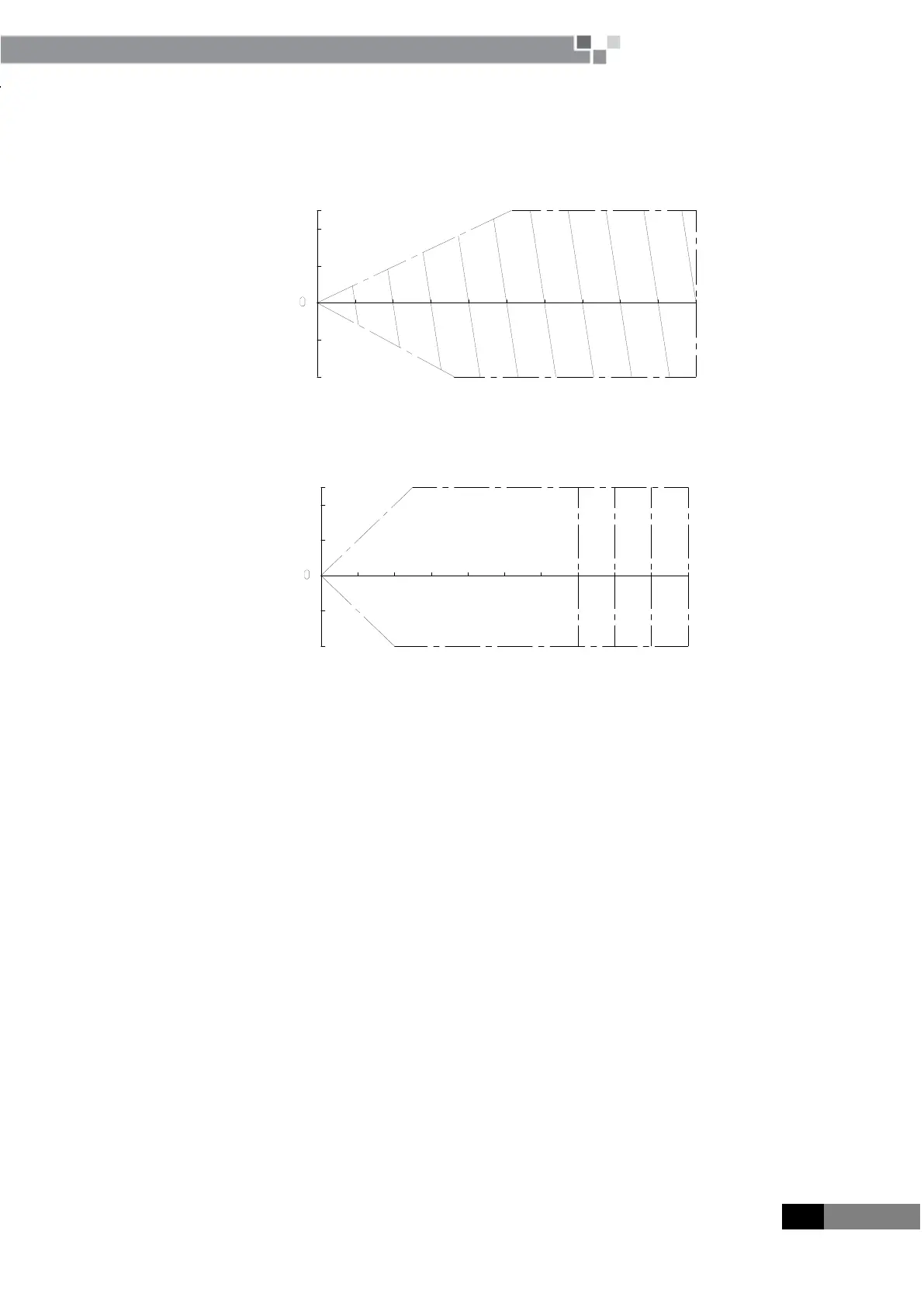
b Variance ratio of heating capacity
20
10
Hm(m)
10
10
Hp(m)
20
25
20 30 5040 60
1.0
70 9080
100
L(m)
0.97
0.92
0.9
Under heating operation, it may frost when there is snow on the outdoor heat exchangers or the outdoor
temperature is below 6℃, which will reduce the heating capability of the unit.
5 PRINCIPLE OF OPERATION
5.1 System Flowchart
As the following system flowchart, princilple of operation is:
Conneting to power supply, the uint stars to work.In cooling, the low-temperature and low-pressure refrigerant
gas from each indoor heat exchanger will be merged and inhaled by the compressor and then become
high-temperature and high-pressure gas, which will later be discharged into outdoor heat exchangers. By
exchanging heat with outdoor air, refrigerant will turn to liquid and flow to each indoor unit via Y-type branch or
manifold. Pressure and temperature of the refrigerant will then be lowered by throttle elements before it flows into
indoor heat exchangers. After exchanging heat with indoor air, refrigerant wil become low-temperature and
low-pressure gas again and repeat the circulation so as to realize the cooling effect. In heating, 4-way valve will be
energized to make refrigerant circulate in a reverse direction of cooling. Refrigerant will release heat in indoor heat
exchangers (electric heating elements will also work under certain circumstance and release heat) and absorb heat
in outdoor heat exchangers circularly so as to realize the heating effect.
 Loading...