DC Inverter U-match Series Cassette Type Unit
28
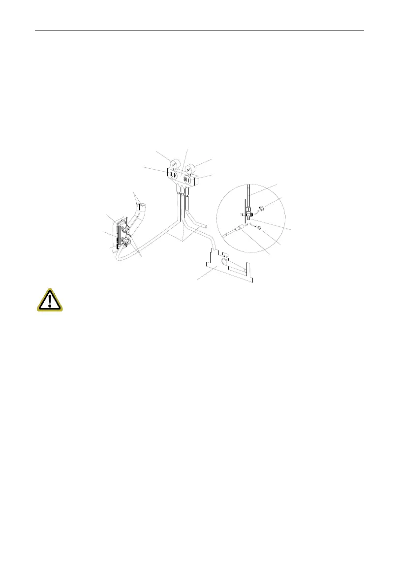
(7) Slightly open the liquid valve and let some refrigerant go to the connection pipe
to balance the pressure inside and outside of the connection pipe, so that air will
not come into the connection pipe when removing the hose. Note that the gas
and liquid valve can be opened fully only after the manifold valve assembly is
removed.
(8) Place back the caps of the liquid valve, gas valve and also the service port.
Hose with the valve pin
gauge manifold
Pressure gauge (Low-pressure)
Pressure gauge (Hi-pressure)
Switch (Low-pressure)
Switch (Hi-pressure)
Connection pipe (to indoor unit)
Liquid valve
Gas valve
Service port
Cap
Hose
Vacuum pump
Cap
Service pipe
Cap
Connection pipe
Notice:
For large-size units, there are maintenance ports for liquid valve and gas valve.
During evacuation, you may connect the two hoses of the branch valve assembly to
the maintenance ports to speed up the evacuation.
3.2.4.2 Leak Detection Methods
The following leak detection methods are deemed acceptable for systems
containing flammable refrigerants.
Electronic leak detectors shall be used to detect flammable refrigerants, but the
sensitivity may not be adequate, or may need re-calibration. (Detection equipment
shall be calibrated in a refrigerant-free area).
Ensure that the detector is not a potential source of ignition and is suitable for
the refrigerant used. Leak detection equipment shall be set at a percentage of the
LFL of the refrigerant and shall be calibrated to the refrigerant employed and the
appropriate percentage of gas (25 % maximum) is confirmed.
Leak detection fluids are suitable for use with most refrigerants but the use of
detergents containing chlorine shall be avoided as the chlorine may react with the
 Loading...