7
3.
4.
5.
1.
2.
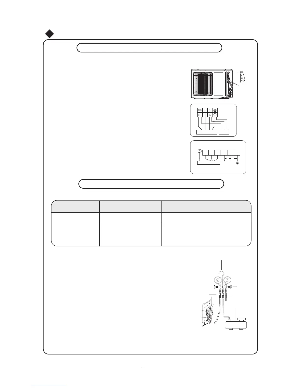
Remove the handle on the right side plate of outdoor unit.
Take off wire cord anchorage. Connect and fix power cord
to the terminal board. Wiring should fit that of indoor unit.
Fix the power cord with wire clamps and then connect the
the corresponding connector.
Confirm if the wire has been fixed properly.
Reinstall the handle.
●
●
Installation of Outdoor Unit
Electric Wiring
NOTE:
Incorrect wiring may cause malfunction of spare part.
After the wire has been fixed, ensure there is free
space between the connection and fixing places
on the lead wire.
real product for authentic information.
Wire hole
Sketch map of power connection wire:
Power connection wire Power cord
Cable-cross board
for 9k、12k unit
for 18K、24K unit
Indoor unit
connection
N(1)
2 3
L1
L1
L2
L2
G
blue
black
brown
POWER
yellow-
green
blue
brown
yellow-
green
Schematic diagram being reference only, please refer to
● Use vacuum pump
1. Connect the charging hose of manifold valve to charging
port of low-pressure valve. Both high-pressure valve and
low-pressure valve must be tighten up).
2. Connect joint of charging hose to vacuum pump.
3. Fully open Lo (low pressure ) handle of manifold valve
and start the vacuum pump for vacuum pumping.
4. Usually the vacuum pumping time of 2600W AC is about
15min. The vacuum pumping time of 5000W AC is about
20min. The vacuum pumping time of 7200W AC is about
30min. Make sure the pressure is -1.0X10⁵pa (-76cmHg).
When vacuum pumping is finished, close Lo (low pressure)
handle of manifold valve completely to stop the vacuum pump.
(Note: R410A refrigerant special vacuum pump should be
applied for R410A unit.)
Liquid
valve
Gas valve
Manifold valve
Multimeter
Piezometer
Hi handle
Lo handle
Charging hose
Charging hose
Vacuum pump
Length of connection pipeAir purging method
Use vacuum pump
Nameplate value
Refrigerant charging amount
Not longer than 24.6ft
24.6~65.6ft
●
Air purging method:
-76cm Hg
Nameplate value +20g/m (for 9k、12k、18k heat pump unit)
Nameplate value +15g/m (for 18k、24k cool only unit)
Nameplate value +50g/m (for 24k
heat pump unit
)
add 15g/20g/50g of refrigerant for additional 1m of pippe length
Air purging
 Loading...