98
Installation and Maintenance
Service Manual
a
b
ProcedureSteps
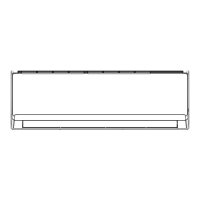
4. Remove electric box cover
electric box cover
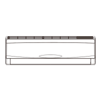
5. Remove front case sub-assy
Remove the screws on the electric box cover
to remove the electric box cover.
Remove the screws fixing front case.
Note:
1.Open the screw caps before removing the
screws around the air outlet.
2.The quantity of screws fixing the front case
sub-assy is different for different models.
Loosen the clasps at left, middle and right sides
of front case. Life the front case sub-assy
upwards to remove it.
screw
screw caps
left clasp
middle clasp
right clasp
screws
front case sub-assy
front case sub-assy
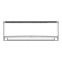
3. Remove horizontal louver
Push out the axile bush on horizontal louver.
Bend the horizontal louver with hand and then
separate the horizontal louver from the
crankshaft of step motor to remove it.
location of step motor
horizontal louver
axile bush
 Loading...