20
Technical Information
Service Manual
1
2
3
4
5
6
7
8
9
10
11
12
13
14
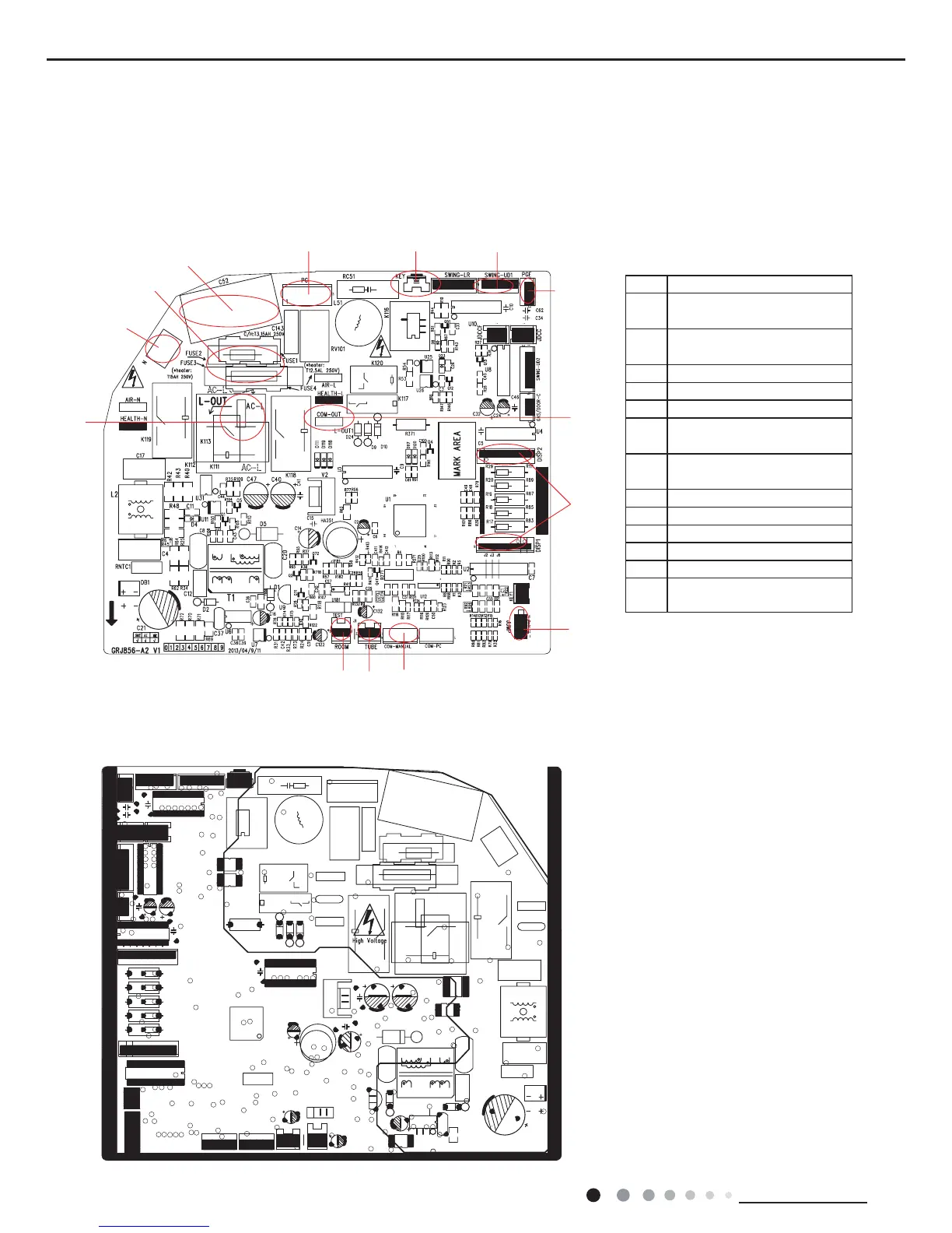
5.2 PCB Printed Diagram
1 Interface of PG motor
2
Up and down swing terminal
interface
3
Feedback interface of indoor
fan
4 Interface of display
5 Jumper cap
6 Wired controller
7
Tube temperature sensor
interface
8
Ambient temperature sensor
interface
9 Live wire interface
10 Neutral wire interface
11 Fuse
12 Fan capacitor
13 Auto button
14
Interface of indoor unit and
outdoor unit communication
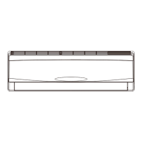
● Top view
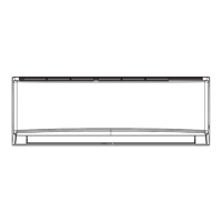
● Bottom view
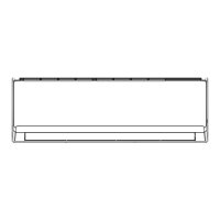
Indoor Unit
GWC18MC-D3DNA3F/I GWC18MC-D3DNA5F/I GWH18MC-D3DNA3F/I GWH18MC-D3DNA8F/I GWH18MC-D3DNA5F/I
 Loading...