Home
Gree
Air Conditioner
GWC24QE-D3DNA1D
Gree GWC24QE-D3DNA1D User Manual
5
of 1
of 1 rating
97 pages
Give review
Manual
Specs
To Next Page
To Next Page
To Previous Page
To Previous Page
Loading...
87
Installation and Maintenance
Service Manual
Steps
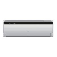
15.Remove left side plate
left side plate
T
wist off the screws connecting the left side plate
and chassis with screwdriver
, and then remove
the left side plate.
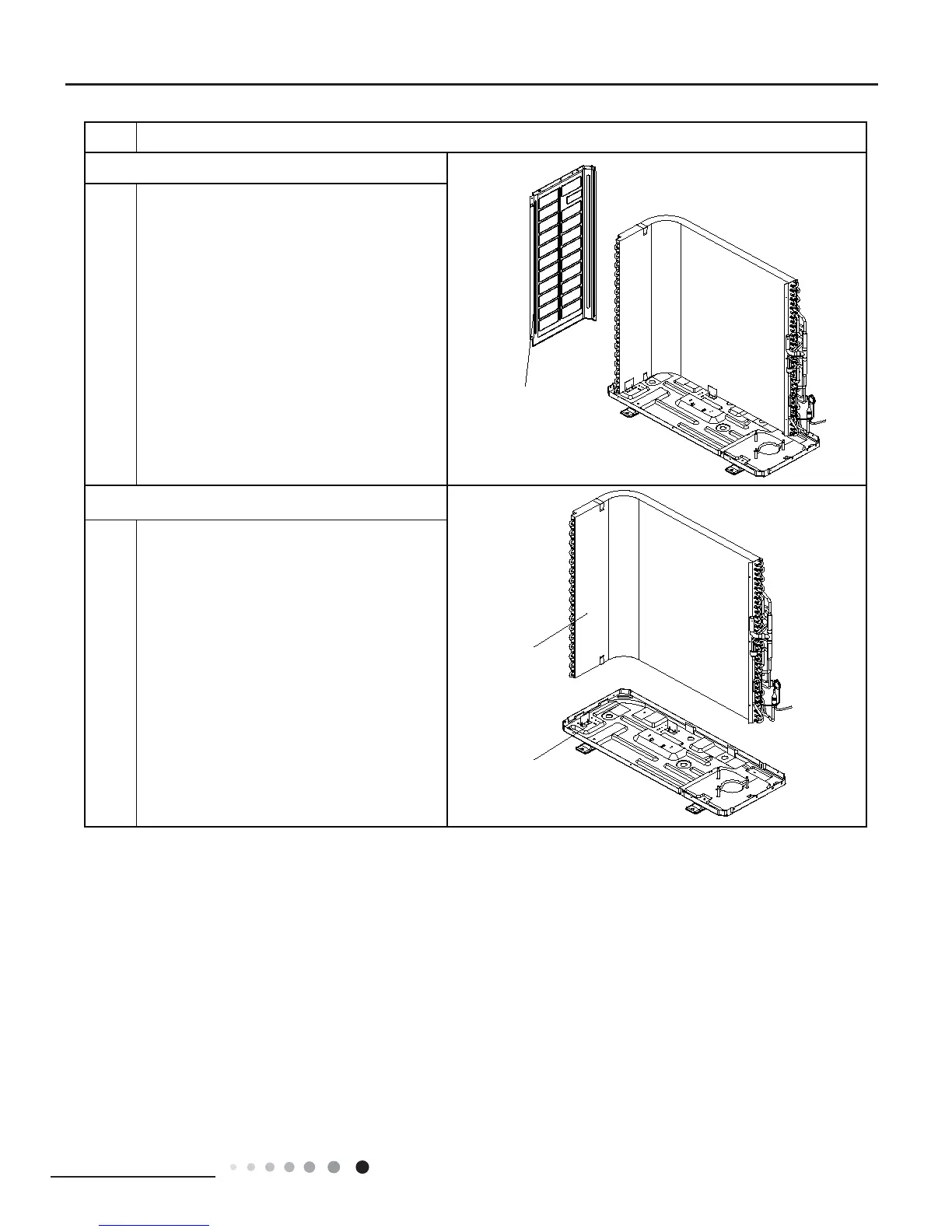
Pull it upwards to separate the chassis and
condenser
.
16.Remove chassis and condenser
chassis
condenser
Procedure
90
92
Table of Contents
Default Chapter
2
Table of Contents
2
Part : Technical Information
4
Specifications
5
Operation Characteristic Curve
9
Cooling
9
Heating
9
Capacity Variation Ratio According to Temperature
9
Noise Curve
10
Cooling and Heating Data Sheet in Rated Frequency
10
Indoor Side Noise
10
Outdoor Side Noise
10
1 Summary
4
3 Outline Dimension Diagram
11
Indoor Unit
11
Outdoor Unit
12
4 Refrigerant System Diagram
13
5 Electrical Part
14
Wiring Diagram
14
PCB Printed Diagram
17
6 Function and Control
20
Remote Controller Introduction
20
Buttons on Remote Controller
20
Introduction for Icons on Display Screen
20
MODE Button
21
FAN Button
21
SWING Button
21
TURBO Button
21
SLEEP Button
23
TEMP Button
23
I FEEL Button
23
LIGHT Button
23
Function Introduction for Combination Buttons
24
Energy-Saving Function
24
Heating Function
24
Operation Guide
24
Brief Description of Modes and Functions
25
Basic Function of System
25
Cooling Mode
25
Drying Mode
25
I Feel Control Mode
26
Compulsory Defrosting Function
26
Refrigerant Recovery Function
26
Ambient Temperature Display Control Mode
26
Input Parameter Compensation and Calibration
27
Check Effective Judgment Controls of Parameters
27
Temperature Setting Range
27
Dehumidifying Mode
27
Outdoor Units
27
Special Functions
28
Defrosting Control
28
Conditions for Starting Defrosting
28
Control Logic
28
Starting Estimation
29
Frequency Limited
29
Reducing Frequency at Normal Speed
29
Reducing Frequency at High Speed
29
Reducing Frequency at Normal Speed and Stopping Machine
30
Reducing Frequency at High Speed and Power Turn-Off
30
Voltage Sag Protection
31
Communication Fault
31
Module Protection
31
Module Overheating Protection
31
Starting-Up Failure Protection for Compressor
32
Out-Of-Step Protection for Compressor
32
Voltage Abnormity Protection for DC Bus
32
Abnormity Protection for Four-Way Valve
32
Electric Heating Function of Chassis
33
Electric Heating Function of Compressor
33
7 Notes for Installation and Maintenance
34
Installation Safety Precautions
34
Safety Precautions
34
Main Tools for Installation and Maintenance
35
Installation Dimension Diagram
36
Installation Procedures
37
Start Installation
37
Electric Connection Requirement
38
Installation of Indoor Unit
38
Installation Parts-Checking
38
Selection of Installation Location
38
Connect the Pipe of Indoor Unit
39
Install Drain Hose
39
Install Wall-Mounting Frame
39
Outlet Pipe
39
Bind up Pipe
40
Connect Wire of Indoor Unit
40
Hang the Indoor Unit
40
Connect Outdoor Electric Wire
41
Fix Outdoor Unit
41
Installation of Outdoor Unit
41
Neaten the Pipes
41
Check after Installation and Test Operation
42
Preparation of Test Operation
42
Use Vacuum Pump
42
Vacuum Pumping and Leak Detection
42
9 Maintenance
43
Precautions before Maintenance
43
Error Code List
44
Malfunction of Temperature Sensor F1, F2
47
Troubleshooting for Main Malfunction
47
Malfunction of Blocked Protection of IDU Fan Motor H6
48
Malfunction of Protection of Jumper Cap C5
49
Communication Malfunction E6
50
Key Detection Point
51
Capacity Charging Malfunction
52
Main Detection Point
52
Diagnosis for Anti-High Temperature, Overload Protection
55
Diagnosis for Failure Start up Malfunction
56
Diagnosis for Compressor Synchronism
57
Diagnosis for Overload and Discharge Malfunction
58
Communication Malfunction
59
Diagnosis Process for Outdoor Communication Circuit
60
Air Conditioner Can't be Started up
61
Horizontal Louver Can't Swing
61
Poor Cooling (Heating) for Air Conditioner
61
Troubleshooting for Normal Malfunction
61
Abnormal Sound and Vibration
62
Air Conditioner Is Leaking
62
Compressor Can't Operate
62
ODU Fan Motor Can't Operate
62
10 Exploded View and Parts List
63
Indoor Unit
63
24K Unit
65
11 Removal Procedure
75
Removal Procedure of Indoor Unit
75
Removal Procedure of Indoor Unit
76
Removal Procedure of Outdoor Unit
81
Remove Big Handle,Valve Cover and Top Cover
86
Remove Top Panel
86
Remove Front Side Panel
86
Remove Grille and Panel
87
Remove Right Side Plate
87
Remove Axial Flow Blade
87
Remove Electric Box
88
Remove Motor
88
Remove Motor Support
89
Remove Isolation Sheet
89
Remove Gas Valve and Liquid Valve
90
Remove Valve Support
90
Remove Compressor
90
Remove Left Side Plate
91
Remove Chassis and Condenser
91
Reference Sheet of Celsius and Fahrenheit
92
Set Temperature
92
Ambient Temperature
92
Appendix
92
Pipe Expanding Method
93
Appendix 3: Pipe Expanding M
93
List of Resistance for Temperature Sensor
94
Appendix 4: List of R
94
5
Based on 1 rating
Ask a question
Give review
Questions and Answers:
Need help?
Do you have a question about the Gree GWC24QE-D3DNA1D and is the answer not in the manual?
Ask a question
Gree GWC24QE-D3DNA1D Specifications
General
Brand
Gree
Model
GWC24QE-D3DNA1D
Category
Air Conditioner
Language
English
Related product manuals
Gree GWC24QE-D3DNA6E/I
98 pages
Gree GWC24QE-D3DNA5E/I
98 pages
Gree GWC24QE-D3DNA6E/O(LC)
98 pages
Gree GWC24QE-D3DNB4E/I
98 pages
Gree GWC24QE-D3DNB2E/I
98 pages
Gree GWC24QE-D3DNB2R/O
223 pages
Gree GWC24MD
32 pages
Gree GWC24ND-K3NNB3B
34 pages
Gree GWC07NA-K3NNB1A
34 pages
Gree GWC09KF-D3DNA5A
78 pages
Gree GWC09AB-D3DNA2D
24 pages
Gree GWC36QF-D3DNB4G
115 pages