73
Installation and Maintenance
Service Manual
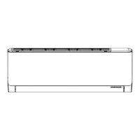
Some models may not contain some parts, please refer to the actual product.
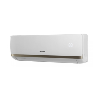
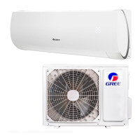
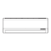
GWH18AGCXD-K3NNA1B/O
The component is only for rererence;please refer to the actual product
1
2
3
4
5
6
7
8
9
10
11
12
13
14
15
16
17
18
19
20
23
22
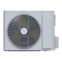
NO. Description
1 Front Grill
2 Cabinet
3 Axial Flow Fan
4 Fan Motor
5 Chassis Sub-assy
6 Clapboard Assy
7 Compressor and Fittings
8 Valve Support Block
9 Valve Cover
10 Valve Support
NO. Description
11 Cut-off valve 1/2(N)
12 Cut-off valve 1/4(N)
13 Handle (Right)
14 Right Side Assy
15 4-Way Valve Assy
16 Condenser Assy
17 Rear Grill
18 Top Cover Assy
19 Motor Support Sub-Assy
20 Left Side Plate
NO. Description
21 Throttle Valve Sub-assy
22 Terminal Board
23 Electric Box Assy
 Loading...