175
Installation and Maintenance
Service Manual
Step Procedure
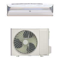
7. Remove isolation plate
Remove the 2 screws connecting the isolation plate and
condenser side plate; remove the 3 screws connecting
the isolation plate and chassis, and then remove the
isolation plate.
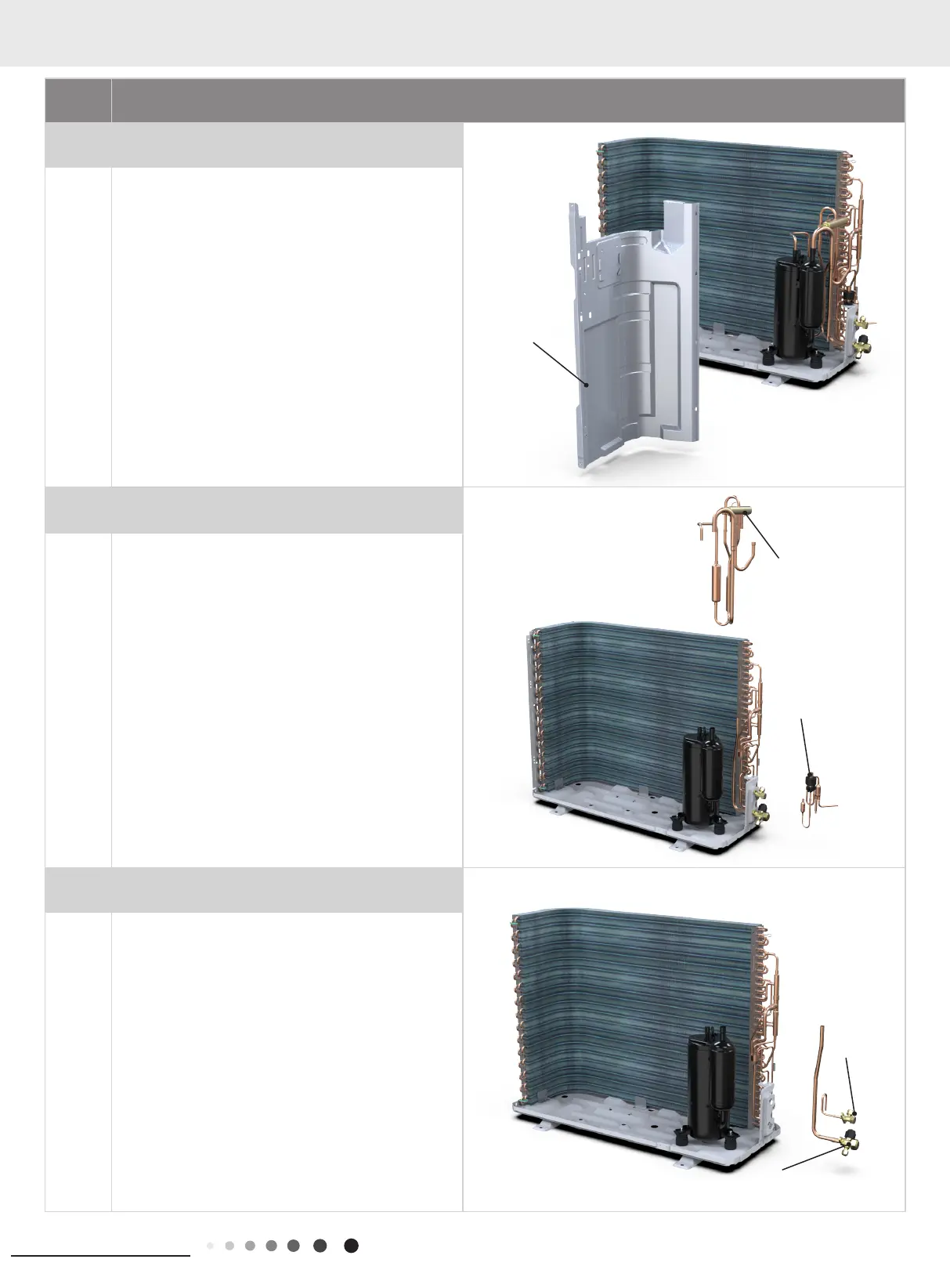
8. Remove 4-way valve assy and electronic
expansion valve assy
Unsolder the welding joints connecting electronic
expansion valve assy the 4-way valve assy with
capillary sub-assy, compressor and condenser; remove
the electronic expansion valve assy and 4-way valve.
Note:
Before unsoldering the welding joint, wrap the 4-way
valve with a wet cloth completely to avoid damage to
the valve caused by high temperature.
9.Remove liquid valve and gas valve
Unsolder the welding joint connecting the valve with
capillary and condenser; unsolder the welding joint
connecting the gas valve and air-return pipe; remove
the 2 screws fixing the gas valve to remove the gas
valve.
Unsolder the welding joint connecting the liquid valve
and Y-shaped pipe; remove the 2 screws fixing the
liquid valve to remove the liquid valve.
Note:
Before unsoldering the welding joint, wrap the gas
valve with a wet cloth completely to avoid damage to
the valve caused by high temperature.
isolation plate
Liquid valve
electronic expansion
valve assy
Gas valve
4-way valve assy
 Loading...