EasyManua.ls Logo

Gree GWH09MA-K3DND3L

Gree GWH09MA-K3DND3L
89 pages
To Next Page IconTo Next Page
Loading...
GREE ELECTRIC APPLIANCES,INC.OF ZHUHAI
Change for Life
Service Manual
GWH09MA-K3DNA3L
GWH09MA-K3DNA4L
GWH09MA-K3DNB7L
GWH09MA-K3DND3L
GWH09MA-K3DNC9L
GWH09MA-K3DNB3L
GWH12MA-K3DNA3L
GWH12MA-K3DNB3L
Models:
GWH12MA-K3DNB7L
GWH12MA-K3DNC9L
GWH12MA-K3DND3L
(Refrigerant:R410A)

Table of Contents

Question and Answer IconNeed help?

Do you have a question about the Gree GWH09MA-K3DND3L and is the answer not in the manual?

Gree GWH09MA-K3DND3L Specifications

General IconGeneral
BrandGree
ModelGWH09MA-K3DND3L
CategoryAir Conditioner
LanguageEnglish

Summary

1. Summary

2. Specifications

2.1 Specification Sheet

Table detailing electrical and physical specifications for indoor and outdoor units.

2.2 Operation Characteristic Curve

Graphs showing operational characteristics like current vs. compressor speed.

2.3 Capacity Variation Ratio According to Temperature

Charts illustrating how cooling and heating capacity changes with temperature.

2.4 Cooling and Heating Data Sheet in Rated Frequency

Data table for cooling and heating performance at rated conditions.

2.5 Noise Curve

Graphs showing noise levels for indoor and outdoor units at different speeds.

3. Outline Dimension Diagram

3.1 Indoor Unit

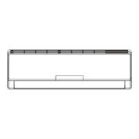
Detailed dimensional drawings for the indoor unit.

3.2 Outdoor Unit

Detailed dimensional drawings for the outdoor unit.

4. Refrigerant System Diagram

5. Electrical Part

5.1 Wiring Diagram

Diagrams showing electrical connections for indoor and outdoor units.

5.2 PCB Printed Diagram

Layout diagrams of printed circuit boards for indoor and outdoor units.

6. Function and Control

6.1 Remote Controller Introduction

Description of the remote controller buttons and icon displays.

6.2 Brief Description of Modes and Functions

Explanation of operating modes and system protections.

7. Notes for Installation and Maintenance

8. Installation

8.1 Installation Dimension Diagram

Diagrams illustrating required clearances and spacing for unit installation.

8.2 Installation Parts-checking

List of parts to check before installation.

8.3 Selection of Installation Location

Guidelines for choosing appropriate locations for indoor and outdoor units.

8.4 Electric Connection Requirement

Specifications and safety guidelines for electrical connections.

8.5 Installation of Indoor Unit

Step-by-step instructions for installing the indoor unit.

8.6 Installation of Outdoor Unit

Step-by-step instructions for installing the outdoor unit.

8.7 Vacuum Pumping and Leak Detection

Procedures for system vacuuming and refrigerant leak detection.

8.8 Check after Installation and Test Operation

Final checks and procedures for testing the unit after installation.

9. Maintenance

9.1 Malfunction Analysis

Troubleshooting guide for common malfunctions and their causes.

9.2 Flashing LED of IndoorOutdoor Unit and Primary Judgement

Explains LED indicators and error codes for fault diagnosis.

9.3 How to Check Simply the Main Part

Basic troubleshooting steps for common component failures.

10. Exploded View and Parts List

10.1 Indoor Unit

Exploded view and parts list for the indoor unit.

10.2 Outdoor Unit

Exploded view and parts list for the outdoor unit.

11. Removal Procedure

11.1 Removal Procedure of Indoor Unit

Detailed steps for disassembling the indoor unit.

11.2 Removal Procedure of Outdoor Unit

Detailed steps for disassembling the outdoor unit.

Appendix 1: Reference Sheet of Celsius and Fahrenheit

Appendix 2: Configuration of Connection Pipe

Appendix 3: Pipe Expanding Method

Appendix 4: List of Resistance for Temperature Sensor

Related product manuals