Do you have a question about the Gree GWH09MB-K3DNA4K and is the answer not in the manual?
Provides an overview of the product models and their types.
Details technical specifications for various models, including electrical and performance data.
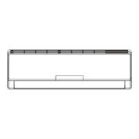
Visual representation of indoor and outdoor unit dimensions for installation planning.
Illustrates the refrigerant flow, components, and operating modes of the system.
Covers wiring diagrams and PCB printed diagrams for electrical connections.
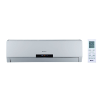
Explains remote controller functions, operating modes, and unit features.
Important safety precautions and guidelines for installation and maintenance procedures.
Step-by-step instructions for installing the indoor and outdoor units, including location selection.
Information on error codes, troubleshooting for malfunctions, and routine maintenance.
Detailed exploded views and part lists for indoor and outdoor units for repair identification.
Step-by-step procedures for removing components of the indoor and outdoor units.
Conversion table for temperature units, useful for understanding specifications.
Details on connection pipe specifications, length, and refrigerant charging based on capacity.
Guide on the correct method for expanding pipes to prevent refrigerant leakage.
Tables listing resistance values for temperature sensors at different temperatures for troubleshooting.
| Brand | Gree |
|---|---|
| Model | GWH09MB-K3DNA4K |
| Category | Air Conditioner |
| Language | English |