71
Installation and Maintenance
Service Manual
Step Procedure
3.Remove display and panel
4.Remove detecting plate and electric box cover2
5.Remove front case sub-assy
6. Remove vertical louver
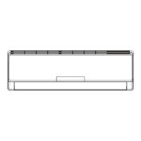
Panel rotation
Screws
Display
Panel
Groove
Screws that are locking the display board.
Separate the display board from the front
panel.
Open the front panel; separate the panel
rotation shaft from the groove xing the
front panel and then removes the front
panel.
Remove the screws xing front case.
Loosen the clasps of front case Life the
front case sub-assy upwards to remove
it.
Loosen the connection clasps between
vertical louver and bottom case to
remove vertical louver.
a.
b.
Screw
Screws
Electric box cover 2
Clasps
Front case sub-assy
Clasps
Vertical louver
Remove the screws xing detecting plate
and remove detecting plate.
Remove the screws fixing electric box
cober2 and remove electric box2.

 Loading...