Do you have a question about the Gree GWH12KF-D3DNA5A and is the answer not in the manual?
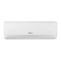
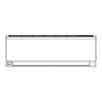
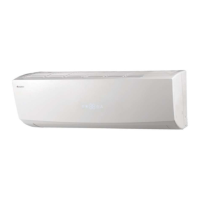
Lists indoor unit models with related specifications and images.
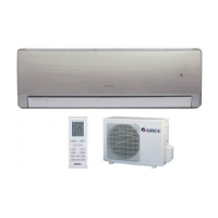
Lists outdoor unit models with related specifications and images.
Shows the remote control and its model number.
General safety instructions to follow before starting installation or service.
Explains the meaning of 'Warning' and 'Caution' symbols used in the manual.
General safety warning about electrical work and proper grounding.
Safety cautions regarding installation location, water, transportation, and operation.
Detailed specifications for indoor units, including capacity, power, dimensions, and performance.
Graphs showing compressor speed vs. current for cooling and heating.
Graphs illustrating capacity variation based on outdoor temperature for cooling and heating.
Table listing operating conditions for cooling and heating modes.
Graphs showing noise levels for indoor fan speed and compressor frequency.
Dimensional drawings and views of the indoor unit.
Dimensional drawings and views of the outdoor unit.
Meaning of symbols and color codes for electrical wiring.
Circuit diagrams for indoor and outdoor units.
Top and bottom views of the indoor unit's control PCB with component labels.
Detailed explanation of remote controller buttons and their functions.
Guide for replacing remote batteries and understanding unit displays and indicators.
Explains cooling, dry, fan, heating, auto, louver, sleep, timer, turbo, health, and I Feel functions.
Covers sensor protection, frequency, pipe, current, freeze-up, defrost, and fan controls.
Emphasizes that installation must be done by qualified personnel following local rules.
Lists conditions to avoid for placement and necessary installation tools.
Provides guidelines for selecting installation positions for indoor and outdoor units.
Specific advice for indoor unit placement to ensure proper airflow and drainage.
Recommendations for outdoor unit placement regarding ventilation and noise.
Details the process of installing the indoor unit mounting plate.
Instructions for installing the outdoor unit, including drain water management.
Instructions for managing drain water from the outdoor unit, especially in cold weather.
Steps for connecting pipes and evacuating air from the system.
Procedures for testing the unit after installation, including gas leak checks.
Methods for checking refrigerant connections for leaks.
Steps for performing a test run and checking basic unit functions.
Exploded view and parts list for the indoor unit.
Exploded view and parts list for the outdoor unit.
Safety guidelines before performing maintenance or inspection on the unit.
Steps to confirm power supply and voltage before troubleshooting.
How to diagnose issues based on LED error codes.
Troubleshooting steps for common issues like fan not rotating or sensor malfunction.
Visual guide to 2-way and 3-way valves and their operation states.
Step-by-step guide for disassembling and removing the indoor unit.
Step-by-step guide for disassembling and removing the outdoor unit.
Procedures for cleaning the refrigeration system using solvents.
Recommends cleaning the heat exchanger for energy efficiency.
| Brand | Gree |
|---|---|
| Model | GWH12KF-D3DNA5A |
| Category | Air Conditioner |
| Language | English |