23
Technical Information
Service Manual
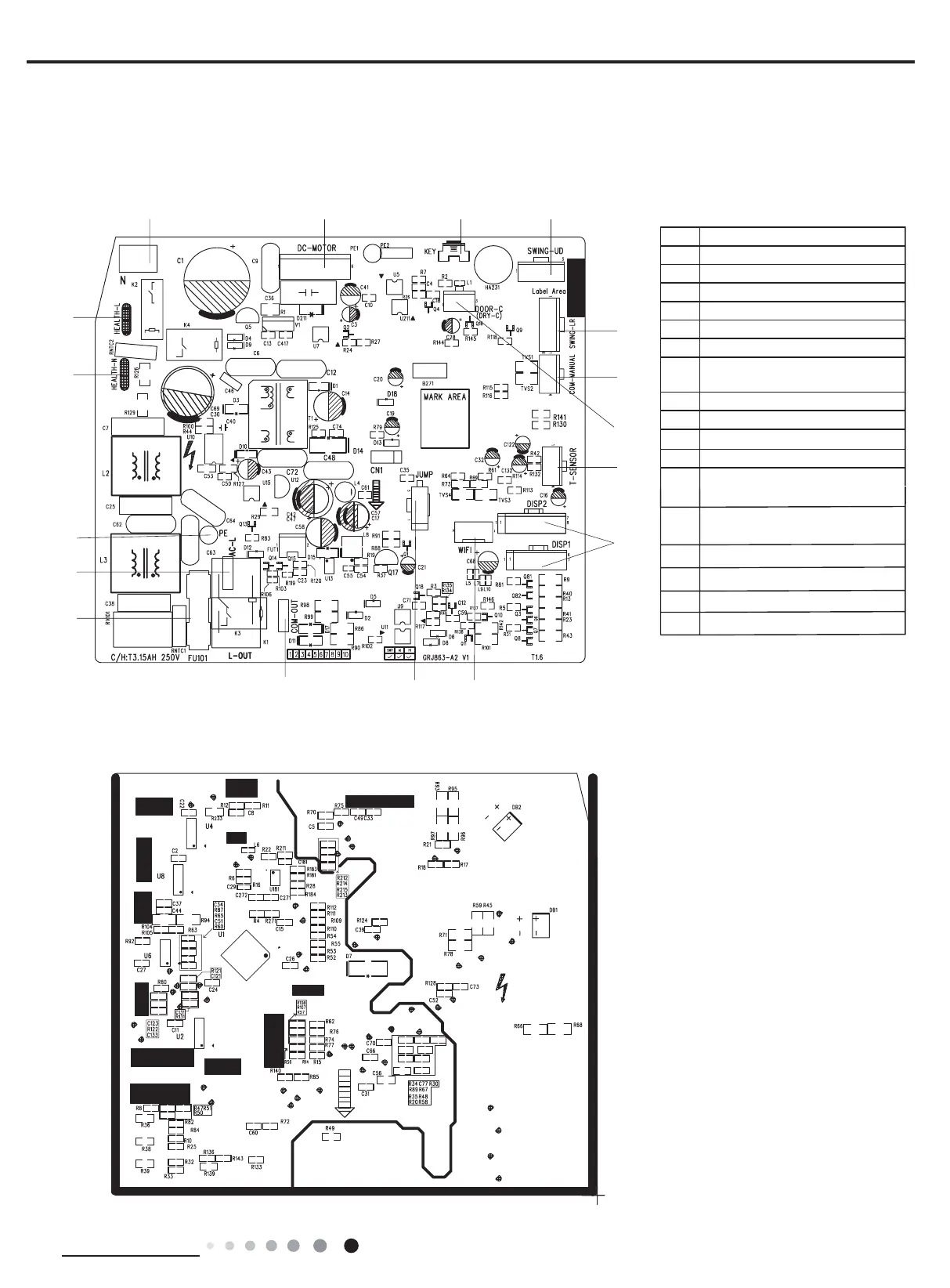
5.2 PCB Printed Diagram
● Indoor Unit
● Bottom view
1234
6
14
15
16
7
817
9
5
No. Name
1 Neutral wire
2 Needle stand for indoor fan
3Auto button
4 Up&down swing interface
5
6Interface of temperature sensor
7
Terminal for display board
connection
8Terminal of jumper cap
9 Communication wire
10
11
Fuse
12
Live wire interface
14
15
16
17
Left&right swing interface
Terminal of wired controlle
Interface of gate control
13
Interface of health function
neutral wire
Interface of health function
live wire
Grounding wire
Detecting plate(WIFI )
 Loading...