Do you have a question about the Gree GWHD24NK3FO and is the answer not in the manual?
Lists the outdoor unit models covered in the manual.
Provides outline dimensions for the GWHD(18)NK3FO model.
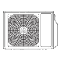
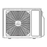
Provides outline dimensions for GWHD(24)NK3FO, NK3GO, and NK3FO models.
Provides outline dimensions for the GWHD(36)NK3BO model.
Provides outline dimensions for GWHD(42)NK3AO and NK3BO models.
Illustrates the refrigerant system for specific NK3FO models.
Illustrates the refrigerant system for specific NK3BO/NK3AO models.
Details electrical wiring configurations for outdoor units.
Shows printed circuit board layouts for various models.
Details operational modes like cooling, dry, heating, and fan.
Explains various protection mechanisms against malfunctions.
Details operational and protection functions specific to 36K/42K models.
Protection triggered by high system pressure.
Protection triggered by low system pressure.
Protection against compressor overload.
Covers functions like refrigerant recovery and master/slave unit setup.
General safety and procedural notes before installation and maintenance.
Outlines the general steps for unit installation.
Details electrical wiring configurations for various models.
Instructions and specifications for connecting refrigerant pipes.
Visual representation of installation dimensions for different models.
A checklist of items to verify post-installation.
Guidelines for selecting installation sites and important considerations.
Step-by-step guide for installing the outdoor unit.
Specifications and procedures for connecting indoor and outdoor units.
Procedures for refrigerant charging and system trial operation.
Essential safety measures before performing maintenance.
Interpreting LED indicators and performing initial malfunction diagnosis.
Troubleshooting steps for IPM protection issues.
Troubleshooting for PFC protection and capacity charging issues.
Troubleshooting for compressor desynchronization.
Troubleshooting for compressor overload and discharge protection.
Troubleshooting steps for unit start failure.
Troubleshooting for temperature sensor errors.
Troubleshooting for DC fan issues.
Troubleshooting for communication errors.
Troubleshooting for high temperature and overload issues.
Lists common problems, causes, and corrective actions.
Details error codes and their meanings for unit malfunctions.
Diagnostic flowcharts for specific error codes.
Troubleshooting steps for common operational issues.
Visual breakdown of parts for the GWHD(18)NK3FO model.
Visual breakdown of parts for the GWHD(24)NK3FO model.
Visual breakdown of parts for the GWHD(24)NK3GO model.
Visual breakdown of parts for the GWHD(28)NK3FO model.
Visual breakdown for GWHD(36/42)NK3BO/NK3AO models.
Detailed steps for disassembling the GWHD(18)NK3FO unit.
Detailed steps for disassembling GWHD(24)NK3FO/NK3GO/NK3FO units.
Steps to disassemble the unit's cover plate.
Steps to disassemble the unit's front panel.
Steps to disassemble the unit's right side panel.
Steps to dismount the unit's grille.
Steps to disassemble the unit's outer casing.
Steps to disassemble the unit's fan blades.
Reassembly of main parts after disassembly.
Steps to safely disconnect the power cord before work.
Steps to disconnect pipelines from the compressor.
Procedure for removing a faulty compressor.
Installing a new compressor and connecting pipes.
Steps to remove the 4-way valve coil.
Steps to disconnect the 4-way valve from pipes.
Procedure for replacing the 4-way valve.
Steps to install the 4-way valve coil.
Steps to remove the electronic expansion valve coil.
Steps to disconnect the valve from pipes.
Procedure for replacing the electronic expansion valve.
Steps to reconnect the valve with pipelines.
Steps to install the electronic expansion valve coil.
Steps to disconnect the liquid separator.
Procedure for removing the liquid separator.
Installing a new liquid separator and connecting pipes.
Conversion table for temperature scales.
Specifications for refrigerant pipe lengths and capacities.
Instructions for cutting refrigerant pipes to the correct length.
Steps to remove burrs after cutting pipes.
Instructions for applying insulating pipes to connections.
Instructions for installing the union nut.
Procedure for expanding pipe ports using an expander.
Checking the quality of the expanded pipe port.
| Brand | Gree |
|---|---|
| Model | GWHD24NK3FO |
| Category | Air Conditioner |
| Language | English |