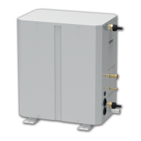
Hydro Box
25
4.5 Connection of Communication Wire for Wired Controller
(1) Detach the electric box lid of Hydro Box.
(2) Let the Communication cable pass through the wiring through-holes.
(3) Connect the communication wire to terminal H1 and H2 of Hydro Box 4-bit wiring board.
(4) Fix the communication cable with clamp of electric box.
4.6 Confirm DIP Switch of Main board
Confirm the S1 and S2 DIP switch on the main board of hydro box. S1
DIP means capacity
DIP switch. S2
DIP means function DIP.
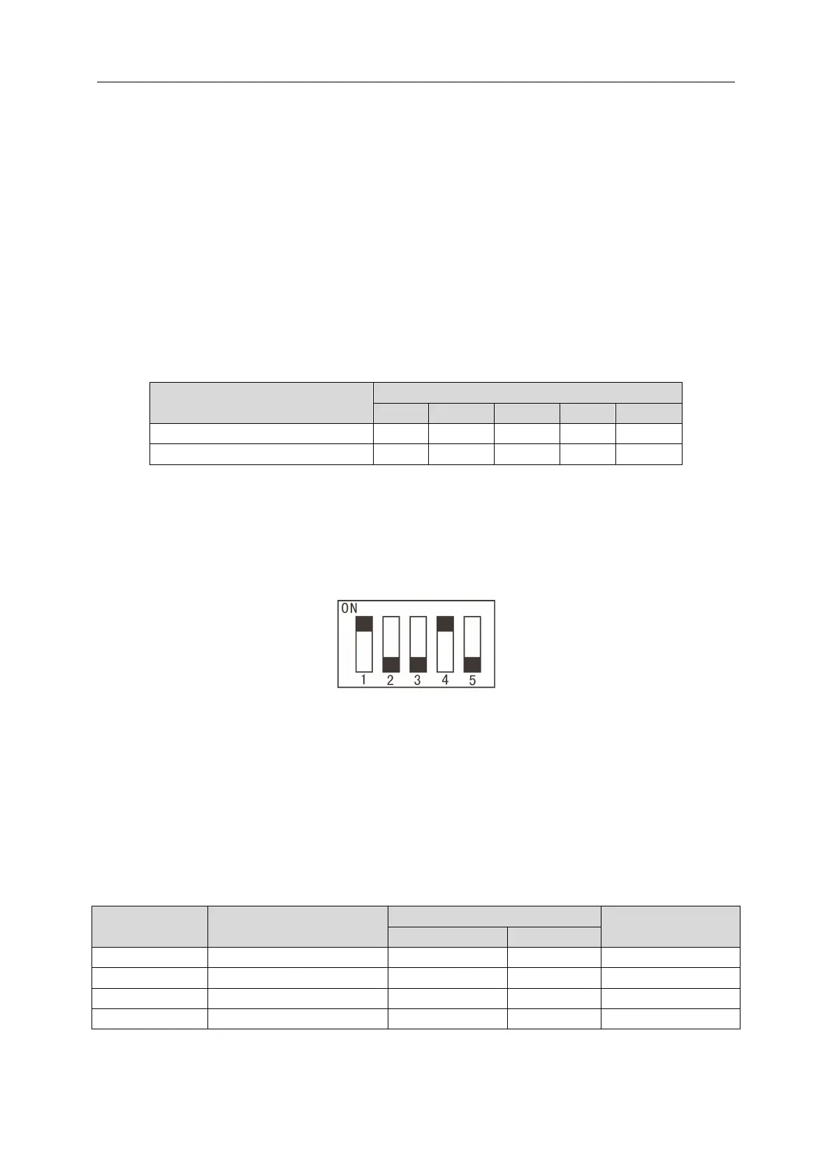
4.6.1 Capacity DIP(S1) of Hydro Box
Capacity DIP switch S1 is 5 bit. Please do not change it.
Capacity of hydro box
Notes:
①
DIP switch shall be set correctly and cannot be set in the middle position. When the
switch is set to “ON”, it means “0”; when the switch is set to the number side, it means
“1”.
Example: S1 of 16kW hydro box is as shown in the following figure:
Fig.4.20
②
The black part is the bar for setting DIP.
4.6.2 Function DIP(S2) of Hydro Box
Function DIP switch S2 is 4 bit. “1”, “2”, and “3” stand for “Gree water tank”, “Floor heating”
and “Solar power” respectively. Each function DIP is as below: Setting to “number” means this
function is connected; setting to “ON” means this function is not connected. “1” and “2” must be set
according to the actual status of project. “3” and “4” cannot be changed. Otherwise, the unit may
occur temperature sensor malfunction or cannot operate.
DIP sequence Meaning
Ex-factory setting
Example: S2 is as shown in the following figure:
 Loading...