EasyManua.ls Logo

Gree KF-70DW/NA1 User Manual

Gree KF-70DW/NA1
43 pages
To Next Page IconTo Next Page
Page #1 background imageLoading...
Page #1 background image
            .......................................................
 
               ...................................................
 
          ........................................................7
  
               ..................................................8
            ......................................................10
                           .......................................12
             .....................................................11
           .......................................................27
10            .....................................................40
                     .............................................35
        ... .....................................................41
KF(R)-70DW/NA1 Technical Service Manual
Introduction
In this technical service manual, you will find rich references to KF(R)-70DW/NA1
model including photoes, technical specifications, explosive views, spare parts lists and
circuit diagrams. Service people and engineers of Gree' s customers and distributors would
find it a very handy source of technical information of our products.
Technical Support Group
Mar.2004
Contents
Summary
Technical and specifications
Names and spare parts
Outlines and installation dimensions
Working principle diagram
Circuit diagram
PCB function manual
Disassemble procedures
Explosive view and spare parts list
Care and maintenance
Trouble shooting
Question and Answer IconNeed help?

Do you have a question about the Gree KF-70DW/NA1 and is the answer not in the manual?

Gree KF-70DW/NA1 Specifications

General IconGeneral
Power Supply220-240V, 50Hz
RefrigerantR410A
Compressor TypeRotary
TypeSplit
Cooling Capacity7000 BTU
Energy Efficiency Ratio (EER)3.2

Summary

Summary

Technical Specifications

Names and Spare Parts

Outlines and Installation Dimensions

Indoor Unit Outlines and Dimensions

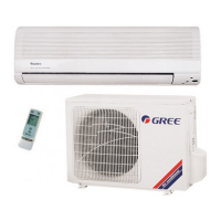
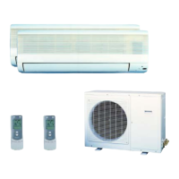
Details external dimensions and clearance requirements for the indoor unit.

Outdoor Unit Outlines and Dimensions

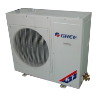
Provides external dimensions and installation clearance for the outdoor unit.

Working Principle Diagrams

Cooling System Diagram (Cooling Only)

Illustrates the refrigerant cycle for cooling-only operation.

Cooling/Heating System Diagram

Explains the refrigerant cycle for both cooling and heating modes.

Circuit Diagrams

PCB Function Manual

Temperature Parameters

Defines the temperature sensors and parameters used by the PCB.

Fundamental Operational Functions

Describes basic operational logic like compressor start/stop delays and mode transitions.

Protection Functions

Details various protection mechanisms against overloads, low voltage, and icing.

Sleep and Timer Functions

Explains the Sleep mode and timer settings for operation scheduling.

Wireless Remote Control and Operations

Details remote control functions, operation modes (COOL, HEAT, DRY, AUTO, TIMER, SLEEP), and usage guidance.

Disassembly Procedures

Indoor Unit Disassembly

Step-by-step guide for disassembling the indoor unit components.

Outdoor Unit Disassembly

Step-by-step guide for disassembling the outdoor unit components.

Explosive Views and Spare Parts Lists

Indoor Unit Explosive View

Illustrates exploded views of indoor unit components.

Indoor Unit Spare Parts List

Lists part numbers and descriptions for the indoor unit.

Outdoor Unit Explosive View

Illustrates exploded views of outdoor unit components.

Outdoor Unit Spare Parts List

Lists part numbers and descriptions for the outdoor unit.

Care and Maintenance

Cleaning and Checks

Provides instructions for cleaning filters, equipment, and performing operational checks.

Troubleshooting

Unit Cannot Start Issues

Diagnoses problems when the air conditioner fails to power on or start.

Poor Cooling/Heating Performance

Addresses common issues causing reduced cooling or heating effectiveness.

Related product manuals