www.enviromaster.com
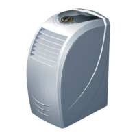
EnviroAir High Wall Ductless Split Systems
11
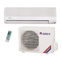
OUTDOOR UNIT INSTALLATION
ENVIROAIR HIGH WALL DUCTLESS SPLIT SYSTEMS
Evacuation
Gauges can now be attached to the service
ports - SERVICE PORTS HAVE A 5/16”
CONNECTION TO GAUGES,
which is dif-
ferent from the norm for R-22. You will need
specific hoses or an adaptor for the 5/16”
connection.
Once the gauges are attached the line
set can be leak checked using Nitrogen
at 300 psig. Evacuate the unit and inter
-
connect down to a minimum of 400-500
Microns, break vacuum with Nitrogen to
further leak check.
Re-evacuate the system down to 300-400
Microns or lower for a period of one hour.
This is an R-410A System it is essential
that a deep vacuum be pulled on the sys
-
Main Power Wiring
Electrical wiring should be done in ac
-
cordance with all National Electrical Code
(NEC) and local state/city building codes.
Note: A small screwdriver is required
for unit terminals.
Breaker size and wiring must be sized
for the rating plate amperage, MCA and
HACR. Use only HACR type breakers,
each system installed must have a sep
-
arate branch circuit with an individual
breaker/fuse.
Electrical Specifications
Nominal
Capacity
Btuh
Volts/Hz/Ph
Compressor Cond Fan Indoor Fan
Total
FLA
MCA
HACR
Max
Fuse
RLA LRA Watts RLA Watts RLA
KWCA/K1CA 09, 12, 18 & 24 Cooling Only
9,000 115/60/1 7.5 47 35 0.81 16 0.35 7.2 10.6 15.0
12,000 115/60/1 9.9 53 45 0.80 16 0.35 9.6 14.0 20.0
18,000 208/230/60/1 6.6 42 60 0.85 40 0.40 6.4 9.5 15.0
24,000 208/230/60/1 10.0 46 60 0.90 40 0.40 8.1 13.8 23.8
KWHA/K1HA 09, 12, 18 & 24 Heat Pump
9,000 115/60/1 7.5 47 35 0.81 16 0.35 7.2 10.6 15.0
12,000 115/60/1 9.9 53 45 0.80 16 0.35 9.6 14.0 20.0
18,000 220/60/1 6.6 42 60 0.85 40 0.40 6.4 9.5 15.0
24,000 208/230/60/1 10.0 46 60 0.90 40 0.40 8.1 13.8 23.8
A local disconnect should be installed ad-
jacent to the outdoor unit in accordance
with National and Local Codes. The out
-
door unit provides power for the indoor
unit, no disconnect is required between
the outdoor and indoor units.
Line voltage from the disconnect should
be wired to:
N - L (115V Unit), + G
L1 - L2 (208/230V Unit), + G
Remove right side knockout on the termi
-
nal access panel for whip/wiring connec
-
tion. Ground connection must be made to
the terminal plate.
Tip: For easier access to the terminals in the
outdoor unit remove the lower access panel to
install whip and sealtite connectors for conduit.
Heat Pump (208/230 V) unit terminals:
L1 - L2 : Power from breaker + G
L3 - L4 : Power to indoor unit + G
1 - 2 - 3 : Control signals
tem to remove all traces of moisture. See
“System Start-Up” section to fine-tune the
refrigerant charge.
These are just examples of typical wiring
connections. Always refer to Wire Diagram
on unit for actual wiring connections.